PATHWAY 3G® Modular Access System Assembly Manual Image shown with multiple ramp and platform handrail options. LIFETIME WARRANTY. Please register at www.ezaccess.com/warranty-satisfaction. © EZ-ACCESS®, a division of Homecare Products, Inc. All rights reserved. All text and images contained in this document are proprietary and may not be shared, modified, distributed, reproduced, or reused without the express written permission of EZ-ACCESS.
PATHWAY 3G® Modular Access System Assembly Manual ATTENTION INSTALLER and END USER For residential use only! 1,000 Lb. weight capacity. Read this manual in its entirety, ensuring you understand all instructions and warnings prior to ramp assembly and use. INSTALLER: Please leave this ASSEMBLY MANUAL with the end user. Please read and become familiar with the ‘MAINTENANCE AND SAFETY’ section of this manual. Fill out online warranty registration.
PROPER SET UP AND USE WARNINGS Read and follow all labels, instructions, and warnings prior to assembly and use. To obtain a copy of complete instructions and warnings, call customer service at 1-800-451-1903. Use caution at all times. Proper maintenance and upkeep to the PATHWAY 3G® Modular Access System and all PATHWAY® system components is vital.
TABLE OF CONTENTS SECTION 1: BASIC SYSTEM COMPONENTS IDENTIFYING COMPONENTS ......................................................................................................................... 5-11 SECTION 2: PLATFORMS INSTALL PLATFORMS ......................................................................................................................................... 12 INSTALL SUPPORT TUBES AND FEET AND ADJUST PLATFORM HEIGHT ......................................................
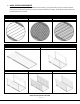
1. BASIC SYSTEM COMPONENTS Because each ramp configuration will differ from one another, your system may or may not contain all these basic system components. Identify your system components before you begin. Check which surface option and handrail options are included.
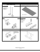
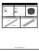
KEY RAMP COMPONENTS PRGT & PRGT48 RAMP GROUND TRANSITION 18” X 36”and 18” X 48” PRLXXPR – RAMP LEG PAIRS XX DENOTES USABLE LENGTH (LENGTHS AVAILABLE 10” THROUGH 100" IN 6” INCREMENTS) SHOWN ASSEMBLED PRHBPR – RAMP HANDRAIL END BRACKET (PAIR) PRRC – CONNECTOR – RAMP TO RAMP INCLUDES COMPONENTS TO CONNECT RAMPS AND RAMP HANDRAILS PRST - RAMP SUPPORT TOP PRHP - RAMP HANGER PAIR USED WHEN LEGS SUPPORT UPPER OR LOWER END OF RAMP ONLY ITEMS NOT SHOWN ACTUAL SIZE Page 6 of 72
KEY RAMP COMPONENTS, CONT’D.
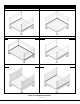
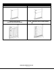
PLATFORMS AND PLATFORM HANDRAIL OPTIONS PLATFORM (STRAIGHT CONFIGURATION) PLATFORM (TURN CONFIGURATION) PLATFORM (8’ X 5’ TURN BACK) PLATFORM* WITH SINGLE-LINE HANDRAIL PLATFORM* WITH VERTICAL PICKET HANDRAIL PLATFORM* WITH HORIZONTAL PICKET HANDRAIL ITEMS NOT SHOWN ACTUAL SIZE *RAMP OR PLATFORM NOT INCLUDED Page 8 of 72
PLATFORMS AND PLATFORM HANDRAIL OPTIONS, CONT’D.
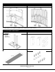
CLOSURE OPTIONS PPCSL – SINGLE-LINE CLOSURE HANDRAIL PPCTL – TWO-LINE CLOSURE HANDRAIL PPCVP4, PPCVP5, PPCVP5 VERTICAL PICKET CLOSURE HANDRAIL PPCHP – HORIZONTAL PICKET CLOSURE HANDRAIL ITEMS NOT SHOWN ACTUAL SIZE Page 10 of 72
ADDITIONAL OPTIONS PTDK – TIE DOWN KIT PUAB – ANGLE BRACE PUCB4, PUCB5 & PUCB8 – UNIVERSAL CROSS BRACE PLP – LANDING PAD PUCB4 USED ON 4’ PLATFORM SIDE PUCB5 USED ON 5’ & 6’ PLATFORM SIDES PUCB8 USED ON 8’ PLATFORM SIDE PUG36 – PATHWAY 3G GATE 36” ITEMS NOT SHOWN ACTUAL SIZE Page 11 of 72
2. PLATFORMS 2.1. INSTALL PLATFORMS If your system does not include a platform, skip to ‘CONNECT RAMP SECTIONS’. Platform handrails are shown for clarity of how to orient platforms in various configurations. It is strongly suggested that all platforms and ramps be installed before installing handrails (see ‘HANDRAILS’ section). 2.1.1. There are four basic platform arrangements (one or more of these platform arrangements may be used in an installation).
2.2. INSTALL SUPPORT TUBES AND FEET, THEN ADJUST PLATFORM HEIGHT 2.2.1. Support tubes, plugs, and feet come in pairs. Support tubes will come in lengths sufficient for the heights at specific locations. 2.2.2. Loosen all set screws in the platform corner pockets. The set screws on the outside of the platform are for the platform support tubes. The set screws on the inside of the platform (one above the deck and one below the deck) are for the handrail posts. 2.2.3.
It is the installer’s responsibility to install the system in a manner which is safe for the persons on and around the system and clearly mark any hazards created by the installation. 2.2.7. Make sure the feet are fully engaged on the tubes and tighten the thumb screw on each foot securely. If installing on soft soil it may be necessary to set the base foot on a concrete pad. 2.2.8.
FIG. 2.6 FIG. 2.
2.4. 45° ANGLE PLATFORM This platform is used between two ramps to make a 45-degree turn and features a symmetrical design, making it usable in either direction. 2.4.1. There are two options for 45° Angle Platform handrails, Two-Line and Vertical Pickets. The platform includes the handrail components needed for the option ordered. Platform handrails are shown for clarity of how to orient platforms in various configurations.
2.6. INSTALL UNIVERSAL ANGLE BRACE - PLATFORMS For added stability, any platform with a walking surface over 36″ high requires bracing. The PUAB (PATHWAY ANGLE BRACE) is used for surfaces 36″ up to 72″. Walking surfaces 72″ and higher requires cross braces in addition to the angle braces. 2.6.1. Angle braces come in pairs. Use four pairs per platform (one pair per support tube, or side) or six pairs when two platforms are connected. 2.6.2.
3. RAMPS 3.1. CONNECT RAMP SECTIONS 3.1.1. Place the walking surface side of the ramp sections face down, onto cardboard or lawn so that the ramp is not damaged (scratched or dented). When installing a single ramp section, skip to 'INSTALL A SINGLE RAMP RUN TO AN EXISTING STRUCTURE’. 3.1.2.
3.2. INSTALL RAMPS ON PLATFORMS 3.2.1. The following will address attaching a ramp or ramp run to a platform. If the ramp needs to be angled with respect to the platform or is going to be attached to an existing porch, skip to ‘ANGLE RAMPS WITH RESPECT TO PLATFORMS, PORCHES, OR DECKS’ in this section. 3.2.2.
3.3. ATTACH RAMP LEGS TO RAMPS 3.3.1. Locate the appropriate PRLxxPR (RAMP LEG PAIR where xx denotes the leg length) for the location. Insert the leg into a foot. Make sure the leg is fully engaged in the foot and the foot will be oriented so it extends under the ramp once installed. Tighten the thumb screw on each foot securely (FIG. 3.5). If installing on soft soil it may be necessary to set the foot on a concrete pad. FIG. 3.5 3.3.2.
FIG. 3.6 3.3.4. Adjust the ramp legs one at a time. ADA guidelines call for a maximum slope of 1:12 (approximately 5°) and this is the ideal slope for the PATHWAY 3G system. However, the ramps can be installed from 1:14 to 1:8 (approximately 4° to 7°). Do not attempt to install the ramps outside this range. 3.3.4.1. Raise the ramp sections (at the center saddle bracket) to take any sag out of the ramp run, then tighten the two locknuts in each leg.
FIG. 3.8 INSTALL UNIVERSAL ANGLE BRACE - RAMPS If the ramp walking surface is over 36″ high, a PUAB (UNIVERSAL ANGLE BRACE) must be installed under the ramp (FIG. 3.8). 3.3.6. The opposite end of the angle brace is attached to the bottom of the ramp (near the center of the tread at the end of the ramp) using a 1/4″ x 1” long self-drilling screw. 3.3.7. Ensure that all angle braces are secured before using the ramp.
3.4. INSTALL GROUND TRANSITION RAMP 3.4.1. The PRGT (RAMP GROUND TRANSITION) consists of two sections that need to be installed into the ramp and connected together. The PRGT (RAMP GROUND TRANSITION) is only designed to transition from the lowest ramp in the run to the ground. Do NOT USE in any other location. 3.4.2. Lift the lowest end of the ramp/ramp run and bring the upper section PRGT into the ramp end tread until the “hook” is engaged FIG. 3.9), then rotate into place (FIG. 3.
3.5. INSTALL A SINGLE RAMP RUN TO AN EXISTING STRUCTURE If installing a ramp run to an existing landing other than a PATHWAY 3G Platform, such as a porch, deck, stairs, etc., follow these steps: 3.5.1. Turn the ramp section upside down on a flat surface. Do this on cardboard or a lawn so that the ramp is not damaged (scratched or dented). 3.5.2. Locate PRHBPR (RAMP HANDRAIL END BRACKET PAIR). Install four end brackets (will be used to attach handrails in a later step).
3.6. ANCHOR RAMP UPPER TRANSITION The PRUT (RAMP UPPER TRANSITION) must be anchored to a substantial surface. Use the pre-drilled holes at each corner of the PRUT (RAMP UPPER TRANSITION) as guides. 3.6.1. IF RESTING ON A WOODEN SURFACE: 3.6.1.1. Secure PRUT (RAMP UPPER TRANSITION) by installing the 1/4″ x 1” long self-drilling screw through each hole (FIG. 3.16) 3.6.2. IF RESTING ON A CONCRETE SURFACE: 3.6.2.1.
3.7. ANGLE RAMPS WITH RESPECT TO PLATFORMS, PORCHES, OR DECKS There are situations where it is necessary to angle ramps with respect to a platform, porch or deck. The components required are not normally included with a typical system unless it is a ramp or ramp run without a platform. If a ramp must be angled when attaching to a platform, a PRUT (RAMP UPPER TRANSITION) or PRLT (RAMP LOWER TRANSITION) with a PRST (RAMP SUPPORT TOP) must be used instead of a PRHP (RAMP HANGER PAIR).
4. HANDRAILS 4.1. RAMP HANDRAILS 4.1.1. Two-line handrails are provided in pairs when ordered with the ramp. Other styles of ramp handrails, Single-Line, Vertical Pickets, and Horizontal Pickets, are provided for a single side to allow maximum flexibility in handrail options. Two-line handrails can also be converted to other styles. 4.1.2. One handrail is required on each side of the ramp but handrails are interchangeable side to side. 4.1.3.
FIG. 4.2 4.2. FIELD CONVERT TWO-LINE RAMP HANDRAILS TO VERTICAL PICKETS 4.2.1. Remove the Two-Line handrail from the ramp (if installed) then remove the lower rail (FIG. 4.3). 4.2.2. Install the vertical pickets into the two uppermost and lowermost holes in the ramp handrail posts using the provided 5/16”-18 x 2-1/4” long hex bolts and 5/16” flat washers.
4.3. ASSEMBLE HORIZONTAL PICKET RAMP HANDRAILS 4.3.1. Assemble the Horizontal Picket ramp handrails before installing on the ramp. 4.3.2. Starting with the uppermost holes, insert a horizontal picket between the ramp handrail frame posts and secure using the 5/16”-18 x 2-1/4” long hex bolts and 5/16” flat washers provided (FIG. 4.4). 4.3.3. Insert the five remaining horizontal pickets in the same manner until all six have been installed.
4.4. ASSEMBLE STANDARD PLATFORM HANDRAILS 4.4.1. Two-Line and Single-Line handrails are provided in pairs when ordered with the PATHWAY 3G platform. Vertical Pickets & Horizontal Pickets are provided for a single side to allow maximum flexibility in handrail options. When Vertical Pickets or Horizontal Pickets are ordered, you will receive a platform with Two-Line handrails and the picket option(s) ordered. Two-Line handrails can also be converted to other styles in the field, see Section 4.6.
4.4.4. For Vertical Picket platform handrails, pre-assemble the handrails by inserting a 5/16”-18 x 1” long hex bolts through a 5/16” flat washer, the angle post, and into a 5/16”-18 round threaded insert in the handrail or square threaded insert in the vertical pickets. Use the holes shown in FIG. 4.7. FIG. 4.7 4.4.5.
4.5. INSTALL STANDARD PLATFORM HANDRAILS 4.5.1. Regardless of the handrail style, but depending on the configuration, refer to FIG. 4.9 and FIG. 4.10 as needed. 4.5.2. Pre-assemble the platform handrail for both sides of a straight configuration and the “first″ handrail of a turn configuration as described above. Make sure the unattached legs of the angle posts are on the same side with respect to the handrail tubes, curb and pickets and pointing outward as shown. 4.5.3.
FIG. 4.10 4.6. CONVERT TWO-LINE PLATFORM HANDRAILS TO OTHER STYLES 4.6.1. To convert a Two-Line Handrail to Vertical Pickets in the field, leave the top handrail in place but loosen the attachment bolts on both sides and remove lower rail and curb. Install the Vertical Pickets in the same manner described in ‘ASSEMBLE STANDARD PLATFORM HANDRAILS’ section. 4.6.2.
FIG. 4.11 FIG. 4.
FIG. 4.13 FIG. 4.
4.8. 45° ANGLE PLATFORM HANDRAILS 4.8.1. There are two options for 45° Angle Platform handrails, Two-Line and Vertical Pickets. The platform includes the handrail components needed for the option ordered. Single-Line and Horizontal Picket handrail options are not available for the 45° Angle Platform. 4.8.2. Assembling either 45° Angle Platform Two-Line or Vertical Pickets handrails should be completed after all ramps and platforms have been set and the ramp handrails installed.
4.8.4. Insert adjustable elbows into both the ramp handrails and the Bolt-On Stub Rails (FIG. 4.16). 4.8.5. Loosen the elbow assembly screws and position the adjustable elbows so they are aligned with the adjustable elbows on the opposite side (but do not tighten), then measure the distance between the two larger round faces. Measure both upper and lower gaps because they could be different and cut tubes accordingly (FIG 4.16). 4.8.6.
4.8.8. Insert one half of the elbow into the ramp handrail and the other half into the leg of the handrail extension above the connector plate (FIG. 4.17). 4.8.9. Center the large hole in the connector plate over the bolt and washer attaching the lower ramp handrail (or over the second hole from the top if no rail is present) and reassemble the adjustable elbow. 4.8.10. Secure the connector plate to the ramp handrail post using a 1/4”-20 x 1” hex washer head self-drilling screw (FIG. 4.17). FIG. 4.17 FIG.
4.8.12. Insert adjustable elbows into the open ramp handrail, the Bolt-On Stub Rail and the open ends of the welded handrail extension (FIG. 4.19). 4.8.13. Align the adjustable elbows and measure and cut the 1-1/2” diameter handrail tubes connecting the ramp handrail and Bolt-On Stub Rail to the handrail extension. Measure both upper and lower gaps because they could be different and cut tubes accordingly.
4.8.16. After installing the ramp handrails, insert the Short Side Vertical Picket on the “short” side of the 45° Angle Platform. Align the bottom of the posts with the bottom of the corner pockets and tighten the set screws securely. Install angle caps on top of the posts. Refer to Section 4.5 for installing platform handrails and attaching angle caps (FIG. 4.20). 4.8.17.
4.8.18. For the “long” side of the 45° Angle Platform there are two welded Vertical Picket panels which are inserted into the corner pockets then bolted together. Left hand and right hand refer to looking at the “long” side from the “short” side. Insert both into their respective corner pockets and align the bottom of the posts with the bottom of the corner pockets. Bolt the two sections together using 5/16”-18 x 1” hex bolts, 5/16” flat washers and 5/16”-18 nylon insert locknuts as shown (FIG 4.22).
4.8.20. Install an adjustable elbow in the last open ramp handrail and align with the adjustable elbow at the split between the Vertical Picket panels. Measure the gap between the large round faces, cut a 1-1/2” diameter handrail tube to fit the gap and install the handrail tube (FIG. 4.24). The procedure for installing the 1-1/2” diameter handrail tubes and adjustable elbows is the same as the installing the closure top rail. 4.8.21.
5. CLOSURES Closures fill the space between ramp handrails and platform posts. Like the ramp and platform handrails, they are available in Two-Line, Single-Line, Vertical Pickets and Horizontal Pickets. As a standard, the closures come with components which require the ramp to be mounted to one side or the other of a platform but the ramp can also be centered or mounted in any location on a platform side except when using the Vertical Picket closure (refer to Section 5.3).
5.4.1. 5.4.2. 5.4.3. 5.4.4. Cut the 1-1/2″ diameter round tube to the length measured less 1/16” (FIG. 5.3). Using a metal file, smooth any sharp edges from the cutting. Disassemble the adjustable elbow by removing the screw, nut and center insert (FIG. 5.4). Install an elbow half into the end of the cut tube which will attach to the ramp handrail and a 5/16”-18 round threaded insert into the end which will attach to the post (FIG. 5.3). 5.4.5.
5.4.7. Install a 5/16″-18 x 1″ hex bolt through a 5/16” flat washer and the upper hole in the angle post into the 5/16”-18 round threaded insert, then tighten all fasteners securely (FIG. 5.6). 5.4.8. Test to ensure elbow is properly secured and attached. If needed, tighten internal set screws to secure more rigidly. 5.4.9. Once the top rail is in place install the 1-1/2” x 2” curb.
FIG. 5.8 FIG. 5.9 5.4.10. Measure the gap between the long leg of the bracket and the post then cut the 1-1/2” x 2” curb to the measured length, less 1/8” to account for the threaded inserts which will be installed after cutting (FIG. 5.8). 5.4.11. Insert 5/16”-18 round threaded inserts into both ends of the curb. Use a rubber mallet or similar tool to fully seat the threaded inserts as needed (FIG. 5.8). 5.4.12.
5.5. TWO-LINE CLOSURE LOWER RAIL 5.5.1. Locate a platform closure bracket. Remove the 5/16″-18 x 2-1/4″ hex bolt and 5/16” flat washer attaching the lower Two-Line ramp handrail then reinstall bolt and washer through the slot in the short leg of the bracket, the ramp handrail post and into the threaded insert in the lower rail.
5.6. VERTICAL PICKET CLOSURE 5.6.1. Vertical Picket closures are specific to the platform size (4’, 5’ and 6’) and come in two pieces which allow the ramp to be mounted to one side or be centered on a platform side. If the ramp is to be centered on a platform additional components are needed. The additional components will come with the closure if specified at the time of order but the closure can be converted to allow the ramp to be centered in the field by ordering a second set of hardware.
FIG. 5.15 FIG. 5.16 FIG. 5.
HORIZONTAL PICKET CLOSURE 5.6.7. The Horizontal Picket closure includes a special bracket which is attached to the ramp handrail post. If the ramp handrail has Horizontal or Vertical Pickets, remove the 5/16″18 x 2-1/4″ hex bolt and 5/16” flat washer attaching the upper and lower rail then reinstall through the slots in the horizontal picket closure bracket as shown in FIG 5.18.
5.6.12. Attach the tube with threaded inserts installed to the platform handrail post and the horizontal picket closure bracket using 5/16”-18 x 1” long hex bolts and 5/16” flat washers but do not tighten fully (FIG. 5.20). 5.6.13. Repeat the steps above until all five 1 1/2″ diameter round tubes and curb have been installed then tighten all fasteners securely.
5.7. TURN BACK CLOSURES 5.7.1. There are three special closures available for filling the space between two ramps in a turn back configuration. The Single-Line and Two-Line Turn Back Closures can be used with platforms of any size but the 8’ x 5’ Vertical Picket Closure can only be used with the 8’ x 5’ platform.
5.7.11. Measure the gap between the long leg of the closure brackets and cut the 1-1/2” x 2” curb to the measured gap length less 1/8” to account for the threaded inserts which will be installed after cutting (FIG. 5.23). 5.7.12. Install 5/16”-18 round threaded inserts into both ends of the cut curb. Use a rubber mallet or similar tool to fully seat the threaded inserts (FIG. 5.23). 5.7.13. Using a metal file, smooth all sharp edges from cutting the curb. 5.7.14.
5.7.15. If installing a Single-Line Turn Back Closure the installation is complete. 5.7.16. If installing a Two-Line Turn Back Closure, a second 1-1/2″ diameter round tube is installed in the second hole from the top of the ramp handrail posts in the same manner as the curb at the bottom. The only difference is the platform closure brackets are secured by installing the 5/16″-18 x 2-1/4″ hex bolts into the threaded inserts in the lower ramp handrail rather than using a locknut (FIG. 5.25). FIG. 5.25 FIG.
6. FINAL PLATFORM/RAMP STEPS AND CHECKS 6.1. SECURE RAMPS TO PLATFORMS 6.1.1. Once positioning of all ramps and platforms, and installation of all handrails, connectors, and end loops are complete, you will need to secure ramps to platforms with Ramp End Clips (included in PRHP - RAMP HANGER PAIR). Use two Ramp End Clips at all locations where ramps meet platforms. 6.1.2. Position each Ramp End Clip with the hole pointing up and oriented as shown (FIG. 6.
INSTALL RAMP HANDRAIL END LOOPS 6.1.6. The PATHWAY 3G® Modular Ramp System may include both upper and lower end loops (FIG. 6.4). Upper and lower end loops are installed in the same manner. If the end loop being installed doesn’t fit correctly (i.e. the connector plate is angled the wrong direction, the lower leg seems too long or short), you are most likely trying to install it on the wrong end of the ramp or ramp run. 6.1.6.1.
6.1.6.1. Install one 1/4” x 1” long hex washer head self-drilling screw through the hole in the connector plate into the ramp handrail post and tighten securely (FIG. 6.6). FIG. 6.6 6.2. INSTALL RAMP HANDRAIL END CAPS 6.2.1. Use plastic end caps when there are any remaining open ends on the handrails (FIG. 6.7). Push them on by hand or use a rubber mallet. If necessary, use construction adhesive to bond the cap to the ramp handrail. FIG. 6.
INSTALL RAMP CORNER PROTECTOR CAPS 6.2.2. Install protective caps over side rail corners by placing one cap on each side at both the top and bottom of the ramp or ramp run (FIG. 6.8). If necessary, use silicone adhesive to bond the cap to the ramp. FIG. 6.8 6.3. TOUCH-UP ARCHITECTURALLY FINISHED HANDRAILS 6.3.1. As needed, use sandpaper (180 grit or equivalent) for blending scratches on architecturally finished handrails. Do not use on painted or powder coated surfaces. 6.3.2.
7. OPTIONAL EQUIPMENT 7.1. RAMP SUPPORT TOP The PRST (RAMP SUPPORT TOP) provides supplemental support at the upper (or lower) end of the ramp. When used, the support top replaces the PRHBPR (RAMP HANDRAIL END BRACKET PAIR). 7.1.1. Attach top support brackets with two 5/16"-18 x 1-1/2" hex bolts and each 5/16" flat washers (FIG. 7.1).
7.2. RAMP LOWER TRANSITION 7.2.1. The lower transition, in combination with an PRST (RAMP SUPPORT TOP) is commonly used to span wider gaps or accommodate larger angular misalignment than can be achieved with an upper transition. It can also be used in place of the ground transition in some situations. Despite being called a lower transition, it can be used at either end of a ramp or ramp run. The lower transition is the larger of the two transitions. 7.2.2.
7.4. LANDING PAD 7.4.1. The PLP (LANDING PAD) is used at the bottom of a ramp or ramp run to assist mobility on soft ground. Contour the ground to remove any high or low areas which would prevent portions of the Landing Pad from contacting the ground. WARNING The Landing Pad is intended for use on the ground only. The underside of the Landing Pad must be fully supported by the ground. It should never be used in an elevated position like a ramp or a platform. 7.4.2.
7.4.4. Lift the lower end of the ramp and install the lower transition as described (see ‘RAMP LOWER TRANSITION), then slide the pad underneath. Make sure the ramp is on the side marked for ramp attachment and ensure that the lower transition extends fully onto the pad. 7.4.5. Attach the lower transition to the pad using the two provided 1/4” self-drilling screws (FIG. 7.7). FIG. 7.
7.5. PLATFORM TIE STRAPS 7.5.1. The PTPS (PLATFORM TIE STRAP) is intended to attach a platform to an existing porch, deck, threshold or platform where there is little or no gap (1/2″ maximum if being installed per ADA Guidelines). 7.5.2. Position straps next to the platform corner pockets, extending equally onto the platform and the existing surface (FIG. 7.8). 7.5.3. Using the strap as a template, mark and drill 1/8″ pilot holes. 7.5.4.
7.6. LIGHTNING GROUND ROD Prior to installing, ensure that any underground electrical conductors, natural gas lines, water/drain lines, and/or other interferences are located and will not hinder the installation. 7.6.1. Since aluminum can conduct electricity, the PLGRK (LIGHTNING GROUND ROD KIT) provides the components needed to ground a ramp system. 7.6.2.
7.7. TIE DOWN The PTDK (TIE DOWN KIT) includes a pair of auger style anchors for mounting the system in soil or through asphalt, plus wire rope and hardware needed to attach the ramp or platform to the anchor. The tie down is designed to anchor the system to resist seismic loading and hurricane strength winds, but is not rated for specific soil conditions or seismic zones.
FIG. 7.11 7.7.1. For platforms, install one tie down at each corner where a support tube is installed (FIG 7.11). 7.7.2. Place a brace band around the support tube approximately 2″ below either the corner pocket of a platform and secure using the 5/16″ square neck carriage bolt 5/16″ nut, and 3/8″ washer. 7.7.3. Place one end of the wire rope between the legs of the brace band and around the square neck carriage bolt then secure the wire rope together using the supplied 3/16″ wire rope clamp. 7.7.4.
Install one of the 5/16″ eyebolts and secure to the ramp using one 5/16″ flat washer and one 5/16″ nut in each hole (FIG. 7.12). 7.7.11. Secure one end of the wire rope to the eyebolts using the supplied 3/16″ wire rope clamps. 7.7.12. Repeat for all locations. FIG. 7.
7.8. GATE 7.8.1. The PUG36 (MODULAR GATE 36”) can be installed to swing either direction. Determine which side the hinge should be on and the direction the gate should swing before starting installation (FIG. 7.13). FIG. 7.13 7.8.2. Using the rubber mallet, tap in the provided round tube plugs into the tubing ends on the gate. (FIG. 7.14). 1-1/2″ DIAMETER TUBE PLUG FIG. 7.14 7.8.3. Position the gate hinge against the vertical handrail post.
7.8.4. 7.8.5. 7.8.6. Remove gravity latch and finger catch from bag. IMPORTANT! Discard the screws included in the same bag as the gravity latch and finger catch, as they will not be used. Instead, use the screws included in the separate hardware bag for the following steps. Center finger catch on the gate square tube opposite the hinge and mark center of holes with a pencil. Drill three 1/8″ holes through one side of the vertical handrail tube (FIG. 7.17).
8. MAINTENANCE & SAFETY 8.1. PERIODIC MAINTENANCE AND SAFETY 8.1.1. Caution should be used at all times. Proper maintenance and upkeep to the ramp surface is vital. 8.1.2. Use ramp only with a qualified helper. 8.1.3. Always use your mobility device’s lap belt. 8.1.4. It is important that you refer to your equipment’s Owner Guide for the proper degree of incline/decline and chair direction before attempting ramp use. Never exceed its recommendations. 8.1.5.
9. DEICING For the safety of all users, it is important to keep your system clear of snow, ice, and other debris. Always follow the deicing agent manufacturer’s directions. EZ ACCESS will not be held responsible for any injuries or damages that arise from the information provided. ALWAYS check with the deicing product’s manufacturer or your local supplier to determine which method is best for your situation. Sodium Chloride (salt) and Calcium Chloride are particularly damaging to newly poured concrete.
Thank you for choosing EZ-ACCESS® for your accessibility needs. We’d love to hear from you! 1-800-451-1903 www.ezaccess.