
Data Sheet


1
FEATURES
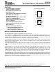
D, DCT, DGK, OR PW PACKAGE
(TOP VIEW)
1
2
3
4
V
CC
SCL1
SDA1
EN
NC
SCL0
SDA0
GND
8
7
6
5
NC No internal connection–
DRG PACKAGE
(TOP VIEW)
1
2
3
4
V
CC
SCL1
SDA1
EN
NC
SCL0
SDA0
GND
8
7
6
5
DESCRIPTION/ORDERING INFORMATION
PCA9515A
DUAL BIDIRECTIONAL I
2
C BUS AND SMBus REPEATER
SCPS150B – DECEMBER 2005 – REVISED OCTOBER 2007
www.ti.com
• Two-Channel Bidirectional Buffers
• I
2
C Bus and SMBus Compatible
• Active-High Repeater-Enable Input
• Open-Drain I
2
C I/O
• 5.5-V Tolerant I
2
C I/O and Enable Input Support
Mixed-Mode Signal Operation
• Lockup-Free Operation
• Accommodates Standard Mode and Fast Mode
I
2
C Devices and Multiple Masters
• Supports Arbitration and Clock Stretching
Across the Repeater
• Powered-Off High-Impedance I
2
C Pins
• Latch-Up Performance Exceeds 100 mA Per
JESD 78, Class II
• ESD Protection Exceeds JESD 22
– 2000-V Human-Body Model (A114-A)
– 200-V Machine Model (A115-A)
– 1000-V Charged-Device Model (C101)
This dual bidirectional I
2
C buffer is operational at 2.3-V to 3.6-V V
CC
.
The PCA9515A is a BiCMOS integrated circuit intended for I
2
C bus and SMBus systems applications. The
device contains two identical bidirectional open-drain buffer circuits that enable I
2
C and similar bus systems to be
extended without degradation of system performance. Both buffers specifically are designed to support the
standard low-level-contention arbitration of the I
2
C bus and support clock stretching.
The PCA9515A buffers both the serial data (SDA) and serial clock (SCL) signals on the I
2
C bus, while retaining
all the operating modes and features of the I
2
C system. This enables two buses of 400-pF bus capacitance to be
connected in an I
2
C application.
The I
2
C bus capacitance limit of 400 pF restricts the number of devices and bus length. Using the PCA9515A
enables the system designer to isolate two halves of a bus, accommodating more I
2
C devices or longer trace
lengths.
The PCA9515A has an active-high enable (EN) input with an internal pullup, which allows the user to select
when the repeater is active. This can be used to isolate a badly behaved slave on power-up reset. It never
should change state during an I
2
C operation, because disabling during a bus operation hangs the bus, and
enabling part way through a bus cycle could confuse the I
2
C parts being enabled. The EN input should change
state only when the global bus and the repeater port are in an idle state, to prevent system failures.
The PCA9515A also can be used to run two buses: one at 5-V interface levels and the other at 3.3-V interface
levels, or one at 400-kHz operating frequency and the other at 100-kHz operating frequency. If the two buses are
operating at different frequencies, the 100-kHz bus must be isolated when the 400-kHz operation of the other bus
is required. If the master is running at 400 kHz, the maximum system operating frequency may be less than
400 kHz, because of the delays that are added by the repeater.
1
Please be aware that an important notice concerning availability, standard warranty, and use in critical applications of
Texas Instruments semiconductor products and disclaimers thereto appears at the end of this data sheet.
PRODUCTION DATA information is current as of publication date.
Copyright © 2005 – 2007, Texas Instruments Incorporated
Products conform to specifications per the terms of the Texas
Instruments standard warranty. Production processing does not
necessarily include testing of all parameters.