
Instructions / Assembly


CAUTION
!
Label all wires prior to disconnection when servicing controls. Wiring errors can cause improper and dangerous operation. VERIFY PROP-
ER OPERATION AFTER SERVICING!
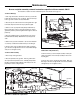
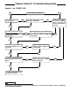
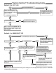
Section 5... the “ECO” LED
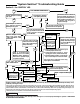
Section 6... the “MAIN VALVE” LED
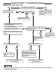
“System Sentinel” Troubleshooting Guide
ECO is “open”. Allow tank to cool,
and reset. If ECO again trips, the
Thermostat/High limit is defective.
Replace as required.
Is “ECO LED now illuminated?
Is the Pilot Flame burning?
Refer to Section 3...the “IGNITION” LED; and
Section 4...the “PILOT VALVE”LED of Trou-
bleshooting Guide. Repair or replace compo-
nents as required.
The ECO (Energy Cut-Off device)
is not tripped (open) and power is
being supplied to the “PV” termi-
nal on the Gas Control Valve.
YES
YES
YES
NO
NO
NO
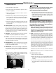
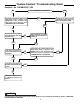
Is the “ECO” LED Illuminated?
Is the Pilot Flame burning?
Is the Spark Ignitor operating?
(Can sparking be heard?)
Ignition Control Module is inoperative and must
be replaced.
Main Gas Valve is inoperative and
must be replaced.
Is the inlet gas pressure at or below the
maximum as specified on the rating plate?
Check Continuity of Blue and White wires
between Ignition Control Module and Gas
Control Valve. Repair or replace as required
to restore power to gas valve.
The Ignition Control Module is
providing 24 VAC between the
“MV” and “MV/PV” terminals on
Gas Control Valve, and Main Burn-
er should be operating
YES
YES
YES
YES
YES
NO
NO
NO
NO
NO
NO
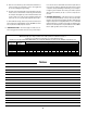
Is the “MAIN VALVE” LED Illuminated?
Is Main Burner on?
Is 24 VAC present between Blue
wire on “MV Terminal and White
wire on “MV/PV” terminal on gas
valve?
Is 24 VAC present between Blue wire on
“MV Terminal and White wire on “MV/PV”
terminal on the Ignition Control Module?
The System Sentinel Panel is
defective and must be replaced.
The System Sentinel Panel is
defective and must be replaced.
20