
Installation Guide
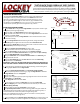

The LockeyUSA Turtle Back TB100 is a hydraulic gate closer designed to push a
gate closed with adjustable hydraulic speed control. Before installing the TB100,
please read instrucons completely and confirm that the gate is in good working
order and operates smoothly. If not, repair gate before mounng the TB100.
TURTLE BACK TB100 HYDRAULIC GATE CLOSER
MOUNTING INSTRUCTIONS:
The LockeyUSA Turtle Back TB100 must mount on the hinge side/pull side
of the gate in order to push the gate closed. The TB100 works best if the
gate has in-line/flush/bu hinges flush with the gate post with 1” or less
gap. For gates with offset hinges or more than a 1” gap, modificaons will
be needed to use the TB100. Visit www.LockeyUSA.com for more opons
and full line of hydraulic gate closers and gate security products.
INSTALLATION INSTRUCTIONS:
1. Place Anchor Bar on the gate with Hinge Bracket on post (works on le or right
hand gates by reversing hinge bracket).
Align the edge of the Hinge Bracket with the edge of the gate post.
Mark and then drill a 3/16” hole in any of the four Hinge Bracket holes and insert
and ghten one 1-1/2” screw.
If the wood post is round, the Hinge Bracket must be morsed into the wood
post for firm mounng.
2. With the Hinge Bracket aached and the gate closed, swing and hold the
Anchor Bar against the gate and trace the outline of the Anchor Bar Slot.
Swing back the Anchor Bar and mark a vercal line ¾” back from the end of the
Anchor Bar Slot (furthest away from hinge).
3. Center the Anchor Connector Plate(B) on the ¾” mark.
Mark the locaon of the two screws and drill 1/8” holes in the gate.
Insert the Clevis Pin(A) into the vercal slot in the Anchor Connector
Plate and aach the Anchor Connector Plate to the gate with two 5/8” screws(C).
Place two Slide Washers(D) onto the Clevis Pin.
Swing the Anchor Bar over the Anchor Connector Plate so the Clevis Pin goes
through the anchor bar slot.
Place the Steel Washer(E) onto the Clevis Pin and install the Coer Pin(F)
through the hole in the Clevis Pin.
IMPORTANT: CHECK THAT THE BAR WORKS WITHOUT BINDING BY SWINGING THE
GATE OPEN AND CLOSED. IF BINDING OCCURS, REMOVE SCREW AND REPOSITION.
4. If the Anchor Bar assembly works freely without binding, finish installing the 3
remaining 1-1/2” Screws into the Hinge Bracket.
5. Locate the Speed Adjustment Knob on the Hydraulic-Spring Assembly.
With the speed adjustment knob facing up, align the Hinge Knuckle in between
the Hinge Bracket and insert a Hinge Bolt.
Secure with a Nut.
Slightly open the gate to get the proper hinge alignment then connect the other
Hinge Knuckle to the Anchor Bar.
Insert Hinge Bolt and secure with a Nut.
6. Open the gate and remove the Wing Key from around the Piston Rod.
Save the Wing Key, as it must be reused should it be necessary to remove the
Hydraulic-Spring Assembly.
Open the gate and allow the Turtle Back to close the gate.
The Speed Adjustment Knob controls the closing speed of the gate. Rotate the
speed adjustment knob clockwise to slow the speed of the gate during close, or
counterclockwise to increase the speed of the gate during close.
(Note: Turn Speed Adjustment Knob in 1/8 turn increments. Increase speed to
overcome a lock set with a strong latch.)
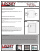
7. Snap the Cover over the Hydraulic-Spring Assembly with the curved end up and
the bent lip on boom, as shown in Diagram 4. Your installaon is now complete.
3/4” mark
Gate Post
Gate
Diagram 1
Diagram 2
Diagram 3
Anchor Bar
Hinge
Bracket
Note: A mechanical gate stop should be installed to prevent
gate from over opening.
Anchor Connector Plate
Anchor Bar Slot
3/4”