
Instructions / Assembly


9
7. VENTING —
NOTE: This unit can be vented either as a Direct
Vent or Power Vent configuration.
NOTICE: This unit can be vented using only the following
recommended pipe material. Use only 2, 3- or 4-inch diameter pipe.
Refer to local codes for restrictions on the use of PVC, CPVC or ABS
pipe and fittings. All exhaust venting materials for product installed in
Canada must meet ULC-S636.
PVC (Schedule 40, ASTM D-1785)
CPVC (Schedule 40, ASTM F-441)
ABS (Schedule 40, ASTM D-2661)(Not permitted in Canada)
PVC Cellular Core (Schedule 40, ASTM F-891)(Not Permitted in
Canada)
The fittings, other than the VENT TERMINAL, should be equiv-
alent to the following:
PVC (Schedule 40 DWV, ASTM D-2665)
CPVC (Schedule 40 DWV, ASTM F-438)
ABS (Schedule 40 DWV, ASTM D-2661)(Not permitted in Canada)
The unit may be vented horizontally through a wall or vertically through
the roof. Pipe runs must be adequately supported along both vertical
and horizontal runs. Maximum unsupported span is recommended to
be no more than 4 feet. It is imperative that the first hanger be located
on the horizontal run immediately adjacent to the first 90-degree elbow
from the vertical rise or at the blower outlet in the case of a horizontal
blower position. Support method used should isolate the vent pipe from
floor joists or other structural members to help prevent the transmis-
sion of noise and vibration. Do not support, pin or otherwise secure the
venting system in a way that restricts the normal thermal expansion and
contraction of the chosen venting material.
If the water heater is being installed as a replacement for an existing power
vented water heater, a thorough inspection of the existing venting system
must be performed prior to any installation work. Verify that the correct
materials, as detailed above have been used, and that the minimum or
maximum vent length and terminal locations as detailed in this manual
have been met. Carefully inspect the entire venting system for any signs
of cracks or fractures, particularly at the joints between elbows or other
fittings and the straight runs of vent pipe. Check the system for signs of
sagging or other stresses in the joints as a result of misalignment of any
components in the system. If any of these conditions are found, they must
be corrected in accordance with the venting instructions in this manual
before completing the installation and putting the water heater into service.
VENT PIPE CONNECTION —
NOTE: This unit can be vented either as a Direct
Vent or Power Vent configuration.
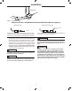
Refer to Figure 3, for connecting the vent pipe to the water heater.
These models can be vented either as a Direct Vent or as a Power Vent
water heater.
NOTICE: If the unit is installed as a Power Vent
water heater, the vent terminal with screen must still
be installed on the inlet air side.
Before starting the vent installation, careful planning should be given
to the routing and termination of the vent pipes. The length of the vent
pipes (inlet and outlet) should be kept to a minimum. Also, see Figure
10 for vent terminal placement. Refer to the venting charts on Table
1, for the pipe sizes that can be used and the total equivalent length
of pipe that can be used. Do not exceed equivalent length of pipe in
charts.
Depending on the size of pipe that is chosen for venting the water
heater, it might be necessary to use a fitting for stepping up or down
in pipe size, to connect to the water heater. All models are shipped
with three ( 3 ) inch vent terminals with screen. If another size of pipe
is used for venting the unit, the proper vent terminal must be installed.
When the unit is vented as a Direct Vent , though a side wall, the vent
terminals must be on the same exterior wall mounted horizontally and
at least twenty-four (24) inches apart (on center). See Figure 10 for
other vent terminal restrictions.
JOINING PIPES AND FITTINGS – All pipe, fittings, solvent
cement, primers and procedures, for the U.S., must conform to
American National Standards Institute and American Society for
Testing and Materials (ANSI/ASTM) standards. For Canada, all pipe,
fittings, solvent cement, primers and procedures must conform to ULC-
S636 and vent manufacture specifications
.
CEMENTING JOINTS – All joints in the vent piping must be properly
sealed and we recommend using the following material:
PVC materials should use ASTM D-2564 grade cement.
CPVC materials should use ASTM F-493 grade cement.
ABS materials should use ASTM D-2235 grade cement.
(ABS is not allowed in Canada)
Cleaner-Primer and Medium Body Solvent Cement
1. Cut pipe end square, remove jagged edges and burrs. Chamfer end of
pipe, then clean fitting socket and pipe joint area of all dirt, grease or
moisture.
2. After checking pipe and socket for proper fit, wipe socket and pipe with
cleaner-primer. Apply a liberal coat of primer to inside surface of socket
and outside of pipe. Do not allow primer to dry before applying cement.
3. Apply a thin coat of cement evenly in the socket. Quickly apply a heavy
coat of cement to the pipe end and insert pipe into fitting with a slight
twisting motion until it bottoms out.
NOTICE: Cement must be fluid; if not, re-coat.
4. Hold the pipe fitting for 30 seconds to prevent the tapered socket from
pushing the pipe out of the fitting.
5. Wipe all excess cement from the joint with a rag. Allow 15 minutes
before handling. Cure time will vary according to fit, temperature and
humidity.
Installation
Figure 3.
—
Vent Pipe Connection Locations