
Installation Guide
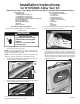

Installation Instructions
for W10704365 4-Way Vent Kit
Parts included in Kit:
1 Instruction Sheet
1 4” Diameter Vent – 305 mm (12”)
1 4” Diameter Vent – 229 mm (9.0”)
1 4” Diameter Vent – 86 mm (3.40”)
1 4” Diameter Vent – Elbow (0 degrees to 90 degrees)
3 4 3/16” Diameter Clamp
2 Plates, Cover (Metal)
2 Plugs, Side Panel (Plastic)
1 Ring, Vent
2 Screws - #8 x 1/2”
Top and Front Load - Dryer Match with Full Front Panel - Side and Bottom Exhaust Venting
(continued)
Instruction Sheet W10712331 Rev. A 10/14
1. Unplug dryer or disconnect power.
NOTE: For gas dryer application, turn off gas supply using the
shut-off valve that supplies the dryer. Disconnect exible gas
supply line connected to rear of dryer.
NOTE: Prior to vent kit installation; determine vent direction and
remove the correct knock-out prior to disassembly of dryer.
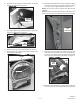
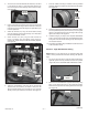
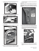
2. Remove console rear plate and rear shelf plate by removing
a total of eight (8) screws. See Figure 1.
WARNING
Electrical Shock
Hazard
Disconnect power before servicing.
Failure to do so can result in death
or electrical shock.
Replace all parts and panels before
operating.
— 1 —
Tool and Accessories required:
®
†
Procedure for Dryer Disassembly
To gain access to inside of dryer for installation of optional
exhaust venting.
3. Remove two (2) screws from the rear of the top. See Figure
2. This will allow the top to be slid rearward.
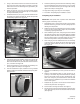
4. Disconnect the door switch connector located in the top left
front corner of the dryer. See Figure 3.
figure 3
CONNECTOR
figure 1
CONSOLE
REAR
PLATE
REAR
PLATE
(3) SCREWS
(5) SCREWS
figure 2
(2) SCREWS
TOP
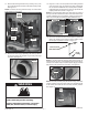
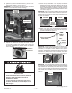
5. Remove the front panel and door assembly by removing a
total of eleven (11) screws: Four (4) ¼” hex-head screws
along the bottom front, three (3) Phillips-head screws around
the door opening, and four (4) T-20 Torx-head screws on
the top front panel bracket. See Figure 4. Once screws are
removed, close the door and lift up the front panel and door
assembly to remove.
figure 4
(4) SCREWS
(4) SCREWS
(3) SCREWS
FRONT
PANEL
†®TORX and T20 are registered trademarks of Acument Intellectual Properties, LLC.