48” TOW-BEHIND LAWN SWEEPER Instructions and Assembly SAVE THESE INSTRUCTIONS FOR FUTURE REFERENCE REV040819 N281
Table of Contents General Warnings and Rules .3, 4 Controls and Features Identification .5 Components and Hardware .. .6, 7 Assembly Instructions .8, 9, 10, 11, 12, 13, 14 Operation Instructions ......15 Maintenance and Storage ..16, 17 Specifications.. ...18 Parts Drawing and Parts List .
GENERAL WARNINGS READ and UNDERSTAND this manual completely before using the Lawn Sweeper. Operator must read and understand all safety and warning information, operating instructions, maintenance and storage instructions, before operating this equipment. Failure to properly operate and maintain the lawn sweeper could result in serious injury to the operator and/or bystanders. Operation Warnings Do not use the sweeper to carry passengers and never sit or stand on the lawn sweeper.
Hazard Signal Word Definitions This is the safety alert symbol. It is used to alert you to potential personal injury hazards. Obey all safety messages that follow this symbol to avoid possible injury or death. DANGER indicates an imminently hazardous DANGER situation which, if not avoided, will result in death or serious injury. WARNING indicates a potentially hazardous WARNING situation which, if not avoided, could result in death or serious injury.
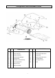
Controls and Features Identification Read this owner’s manual before operating the equipment. Familiarize yourself with the location and function of the controls and features. Save this manual for future reference. 2 1 4 3 1) Hand Lever – Adjusts the brush height. 2) Nylon Hopper – Holds all types of debris. 3) Tires / Wheels – Semi-pneumatic all terrain tires. 4) Hitch – Pin-type design; use only with approved vehicles. .
CAUTION Read and follow all instructions for assembly and operation. Failure to properly assemble this equipment could result in serious injury to the operator and/or bystanders and may cause equipment damage. LAWN SWEEPER COMPONENT PARTS AND ASSEMBLY Before starting to assemble the sweeper, remove all parts from the shipping crate and inspect components to ensure there are no missing or damaged pieces. After inspecting components proceed to “Assembly” and complete steps 1 through 9.
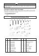
Component and Hardware Parts REF. QTY. REF. QTY.
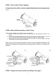
Assembly Instructions STEP 1: Mount Angle Bracket A) Remove the three splint from brush. B) Attach the Angle Bracket (K) to the sweeper housing by using the Hex Bolt M8x16 (F) and the Nylon Lock Nut M8 (G). Tighten securely. NOTE: Before tightening, make sure the angle bracket is aligned straight with the sweeper housing, as shown in the diagram. NOTE: Right-Hand (RH) and Left-Hand (LH) refer to the drivers’ orientation when operating the vehicle.
STEP 3: Secure Hitch Tubes Together Once the Hitch tubes are attached, pass two Hex Bolts M8x75 (A) through the hitch-end (away from the sweeper body) of the tubes to connect them together using two Nylon Lock Nuts M8 (G). Tighten loosely. STEP 4: Mount Hitch Assembly to Hitch Tubes Attach the Hitch assembly in the following order: (see Figure A) A) Mount the angled hitch bracket on top of the hitch tubes, with the straight hitch bracket on the bottom.
STEP 6: Attach Height Adjustment Handle A) Mount the height adjustment handle onto the height adjustment bar. (The height adjustment bar is located outside of the sweeper housing assembly, spanning the wheels.) Use two Hex Bolts M8x40 (C) and Nylon Lock Nuts M8 (G) to firmly attach the handle assembly to the bar. B) Attach the height adjustment strap to the angle bracket (mounted in Step 1). Align the round hole in the height adjustment strap with the angle bracket.
STEP 8: Assemble Hopper Bag A) Unroll the hopper bag and place on the ground with the nylon fabric facing up and the heavy-duty nylon floor facing the ground. B) Inspect the first rear hopper tube (part 15) and locate the brace holes. Pass the tube through the six sewn-in bag loops at the top of the inside of the hopper bag with the brace holes facing downward. C) Pass the upper hopper side tubes through the stitched sleeves on either side of the nylon fabric.
F) On either side, align the ends of the upper and lower hopper side tubes and fasten these together with Clevis Pin Ø9.5x25 (P). Secure with R Pin Ø3 (N). Ø3 R Pin (N) Ø9.5X25 CLEVIS PIN (P) G) Locate the stitched sleeve at the front edge of the bag floor. Insert the bag frame strap into the sleeve. (In some models, the bag frame strap is already inserted into the sleeve.) H) Once inserted, mount the bag frame strap onto the lower hopper side tubes using Clevis Pins Ø6X37 (Q). Secure with R Pin Ø2 (O).
J) Insert the two hopper support rods into the brace holes in the upper and lower rear hopper tubes (part 15). The hopper assembly is now complete. STEP 9: Attach Hopper Bag to Sweeper A) There are two holes in the bar of each of the upper hopper side tubes. Locate the lower hole and pierce the nylon fabric at the location of the lower hole. Note: some models have rivets in the fabric and do not require piercing the fabric.
C) Tie the rope to the upper hopper tube at the center of the bag frame. D) Insert the male ends of the bag arm tubes into the hitch tubes at the back of the sweeper housing assembly (away from the hitch). Secure using Clevis Pins Ø6X42 (R) and R Pin Ø2 (O). E) Remove brush protection boards from inside of sweeper housing assembly. F) Check to see that all bolts are tightened adequately and all pins are mounted securely.
Operation Instructions WARNING Before operating or using the sweeper, review the instructions below and safety information. Failure to follow these instructions may result in property damage and/or injury to the operator or bystanders. Attach the Sweeper to the Towing Vehicle On a level surface, line up the towing vehicle with sweeper. Use the hitch pin and spacers to adjust the height of the tow hitch, as shown in the diagram. Once adjusted, insert the R Pin Ø3 to secure the hitch pin.
Maintenance and Storage WARNING Improper maintenance and storage of the sweeper may void your warranty. MAINTENANCE • • • • • • • • • • After each use clean material out of hopper. Rinse/dry inside and outside of the sweeper after each use. Periodically check all fasteners for tightness and replace any damaged fasteners. Check brushes for debris and keep brushes and brush shaft clean for optimal performance. Twice a year apply a few drops of light multipurpose oil to the brush shaft bearings.
BRUSH REPLACEMENT 1. 2. 3. 4. Remove the hopper bag from lawn sweeper. Only replace one brush at a time. Tip the sweeper forward on housing. Do not remove the hex bolts from double brush retainers. Loosen hex bolts and hex lock nuts from single brush retainers. Slide brush out of retainers, making note of over-lap bristles position. 5. Install new brush, make sure the over-lap bristles are in the same position as before replacement.
Specifications Frame Construction ..Steel Hopper Construction . Nylon Mesh Hitch Type Pin Style Wheel Type Semi-Pneumatic Working Width Wheel Size . . ... .. - 18 - .48” . ..10.
Parts Drawing & Parts List - 19 -
Parts Drawing & Parts List Ref# Drawing No.
Ref# Drawing No. Description 35 GB96/10-DX Big Flat Washer, Ø10 4 36 GB889/M10-DX Nylon Lock Nut,M10 2 37 N280-00032 Hub Cap 2 38 GB5780/M10X85-DX Hex Bolt,M10×85 2 39 N280-00036-DX Spacer Bushing Ø16×3.5 2 40 N280-00012 Pinion Gear R.H. 1 41 N280-00030 Pinion Gear L.H.
Ref# Drawing No. Description Qty 70 N280-00004 Handle Grip 1 71 GB861.
Limited Warranty Limited Warranty YTL International warrants that the product is free from defects in material and workmanship under normal use for one year. For one year from the date of purchase, if the original purchaser finds the product does not conform with this warranty, YTL International shall, at its exclusive option, either repair or replace the product (lawn sweeper).