IR Speed Dome Installation Manual V2.0.
IR Speed Dome Installation Manual 1 Thank you for purchasing our product. If there are any questions, or requests, please do not hesitate to contact the dealer. This manual applies to IR Speed Dome . This manual may contain several technical incorrect places or printing errors, and the content is subject to change without notice. The updates will be added to the new version of this manual. We will readily improve or update the products or procedures described in the manual.
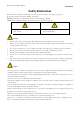
2 IR Speed Dome Installation Manual Safety Instruction These instructions are intended to ensure that the user can use the product correctly to avoid danger or property loss. The precaution measure is divided into ‘Warnings’ and ‘Cautions’: Warnings: Serious injury or death may be caused if any of these warnings are neglected. Cautions: Injury or equipment damage may be caused if any of these cautions are neglected.
IR Speed Dome Installation Manual 3 Preparation for Installation 1. Basic requirements 1) All the electronic operation should be strict compliance with the local electrical safety regulations, fire prevention regulations and other related regulations at the installation place. 2) Check whether all the accessories are there according to the packing list, make sure that the place and installation mode are conform to the demands, if not, please contact the supplier. 3) 2.
4 IR Speed Dome Installation Manual Table of Contents Chapter 1 Installation ................................................................................................................................................... 5 1.1 Check Parts List ............................................................................................................................................. 5 1.2 IR Speed Dome and Network IR Speed Dome Installation .............................................................
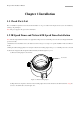
5 IR Speed Dome Installation Manual Chapter 1 Installation 1.1 Check Parts List Prior to installation, unpack the dome unit and check whether it is in good condition and all parts and accessories are included by referring to the packing list. Note: The power supply for the speed dome is AC24V/3A. 1.2 IR Speed Dome and Network IR Speed Dome Installation Note: The following installation instructions are applicable to IR speed dome, network IR speed dome and network high-definition IR speed dome models. 1.
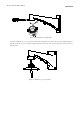
6 IR Speed Dome Installation Manual Figure 1.2.2 Install the fast mounting adapter (3) Before installing the top cover of speed dome, please make sure that both of the lock screws on the fast mounting adapter are slack. Then screw the top cover to the fast mounting adapter and screw up the lock screws by using the L shaped socket screw hexagon wrench. Figure 1.2.
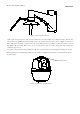
7 IR Speed Dome Installation Manual Figure 1.2.4 Screw up the lock screws 3. Take out the speed dome and tear off the protective sticker from it, as shown in figure 1.2.5. Configure the address, baud rate and other parameters through DIP switch SW1 and SW2 located on the bottom board of the dome, as shown in Figure 1.2.3(the bottom board of IR speed dome), Figure 1.2.4(the bottom board of network IR speed dome) and Figure 1.2.5(the bottom board of network high-definition IR speed dome).
8 IR Speed Dome Installation Manual 1 2 1. Address DIP Switch 2. Protocol DIP Switch 3. Address and Protocol Settings Instruction 3 Figure. 1.2.
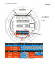
9 IR Speed Dome Installation Manual 1 2 5 1. Address DIP Switch 2. Protocol DIP Switch 3. Address and Protocol Settings Instruction 4. RJ-45 Network Interface 5. SD Slot 4 3 Figure. 1.2.
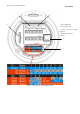
10 IR Speed Dome Installation Manual 1 1. Terminal Resistance Switch 2. RJ-45 Network Interface 3. SD Slot 2 3 Figure. 1.2.
11 IR Speed Dome Installation Manual 4. Cover the sealing ring and tie the safety lanyard to the dome. Note: The sealing ring must be set for the dome’s waterproofing. Figure. 1.2.9 Cover the sealing ring Figure. 1.2.10 Tie the safety lanyard 5. Hang the IR speed dome’s hanging hook to the top cover. Then, connect the integrated cable into the appropriate slots by suggestive identifying information near the slots. The circuit interfaces on the bottom board are shown in figure 1.2.
12 IR Speed Dome Installation Manual Figure. 1.2.11 Hang the dome to the top cover 1. Alarm In/Out Terminals (7 inputs/2outputs) 1 2. Video Out and RS-485 interface 3. 24VAC Voltage Input and GND 2 3 Figure. 1.2.
13 IR Speed Dome Installation Manual 1. Alarm In/Out Terminals (7 inputs/2outputs) 1 2. Audio, Video and 485 Interface 2 3 3. 24VAC Voltage Input and GND Figure. 1.2.13 Bottom circuit board (network IR speed dome) 1. Alarm In/Out Terminals (7 inputs/2outputs) 1 2. Audio, Video and 485 Interface 2 3 3. 24VAC Voltage Input and GND Figure. 1.2.14 Bottom circuit board (network high-definition IR speed dome) 6. Fasten the set screws to fix the IR speed dome.
14 IR Speed Dome Installation Manual Figure. 1.2.10 Fix the IR Speed Dome 1.
15 IR Speed Dome Installation Manual 1.4 DIP Switch Settings Note: The parameters of 485 serial port of network high-definition IR speed dome must be configured in OSD menu, on ‘Remote Setting’ page through client software or in ‘Remote Setting’ page through IE browser. 1.4.1 DIP Switch Settings for IR Speed Dome and Network IR Speed Dome 1 2 1. Address DIP Switch 2. Protocol DIP Switch 3. Address and Protocol Settings 4. Grounding screw 4 3 Figure. 1.4.
16 IR Speed Dome Installation Manual DIP switch settings needed for setting control protocol. Note: If the dome is subject to electromagnetic interference, please remove the grounding screw to disconnect the inner circuit board from the metal case. Initially, the grounding screw is installed acquiescently, so the inner circuit board and the metal case are connected with each other. 1.4.
17 IR Speed Dome Installation Manual 27 ON ON OFF ON ON OFF OFF OFF 28 OFF OFF ON ON ON OFF OFF OFF 29 ON OFF ON ON ON OFF OFF OFF 30 OFF ON ON ON ON OFF OFF OFF 31 ON ON ON ON ON OFF OFF OFF 32 OFF OFF OFF OFF OFF ON OFF OFF 33 ON OFF OFF OFF OFF ON OFF OFF 34 OFF ON OFF OFF OFF ON OFF OFF 35 ON ON OFF OFF OFF ON OFF OFF 36 OFF OFF ON OFF OFF ON OFF OFF 37 ON OFF ON OFF OFF ON OFF OFF 38 OFF ON ON OFF
18 IR Speed Dome Installation Manual 71 ON ON ON OFF OFF OFF ON OFF
19 IR Speed Dome Installation Manual 1.4.3 Baud Rate Settings The positions 1-3 of the DIP Switch SW2 are used for setting the baud rate of the dome. The values are 100, 010, 110, respectively representing 2400bps, 4800bps, 9600bps. If the baud rate is out of the above range, it will be the default setting, 2400bps.
20 IR Speed Dome Installation Manual 1.5 Alarm In/Out Connections The IR speed dome, network IR speed dome can be connected with 7 alarm inputs (0~12VDC) and 2 alarm outputs.
21 IR Speed Dome Installation Manual Chapter 2 Mounts Dimension 2.
IR Speed Dome Installation Manual 2.2 Short Wall Mount 2.
IR Speed Dome Installation Manual 2.
24 IR Speed Dome Installation Manual Chapter 3 Wall Mounting Applications 3.1 Mounting Components Wall Mount Wall mounts are applicable to indoor/outdoor pendant domes. Mounting Accessories Nuts and Flat Washers 3.2 Wall Mounting Instructions The wall mounting is applicable to the indoor/outdoor solid wall construction which should comply with the following mounting requirements: The wall must be thick enough to install the expansion screws.
IR Speed Dome Installation Manual 25 Step1: Drill mounting holes in the wall and install the expansion screws Drill four holes in the wall according to the mounting locations, and then insert M6 expansion screws (not supplied) into the mounting holes. Step2: Secure the wall mount to the wall Drill four hex nuts padding with flat washers through the wall mount and rubber gaskets into the expansion screws.
IR Speed Dome Installation Manual 26 Step3: Install dome to the mount Pass cables through the opening on top of the back box, screw the pipe thread of the back box into the thread hole in the mount, and then use M3 screws to secure the dome. Refer to Section 1.2 for installation instructions. Note: Follow the same instructions described above for the Short Mount installation. For outdoor applications, please adopt the water-proof measures.
IR Speed Dome Installation Manual 27 Step3: Install dome to the mount Note: Follow the same instructions described above for the Short Mount installation. For outdoor applications, please adopt the water-proof measures. The Short Mount is not recommended to be used for outdoor applications.
IR Speed Dome Installation Manual 28 Chapter 4 Corner Mounting Applications 4.1 Mounting Components Wall Mount Wall mount is applicable to the indoor/outdoor pendant domes. It can be used together with corner mount, wall mount or pole mount. Corner Mount The corner mount must be used together with wall mount when it is fixed to the corner.
IR Speed Dome Installation Manual 29 4.2 Corner Mounting Instructions The corner mounting is applicable to the indoor/outdoor 90° solid corner construction which should comply with the following mounting requirements: The wall must be thick enough to install the expansion screws. The wall must be capable of supporting up to 8 times the total load of the dome and its accessories.
IR Speed Dome Installation Manual 30 Step3: Install dome to the mount Pass cables through the opening on top of the back box, screw the pipe thread of the back box into the thread hole in the mount, and then use M3 screws to secure the dome. Refer to Section 1.2 for installation instructions. Note: Follow the same instructions described above for the Short Mount installation. For outdoor applications, please adopt the water-proof measures.
IR Speed Dome Installation Manual 31 Chapter 5 Pole Mounting Applications 5.1 Mounting Components Wall Mount Wall mount is applicable to the indoor/outdoor pendant domes. It can be used together with corner mount, wall mount or pole mount. Pole Mount The pole mount must be used together with wall mount when it is fixed to the pole.
32 IR Speed Dome Installation Manual Pole mount hoop is used to cooperate with pole mount, with following dimensions selectable: φ59-82mm, φ84-108mm, φ103-127mm, φ130-152mm, φ155-178mm, φ180-203mm, φ194-216mm; Customized dimensions can also be provided according to user’s demand. Mounting Accessories Hexagonal Screws (M8×30) and Spring Washers 5.
IR Speed Dome Installation Manual 33 Step2: Install pole mount Pull the power cord, video cable and control line through the opening of the pole mount. Open the hoops and clip them to the pole. Then close the hoops and screw the screws tightly. Note: For outdoor applications, please apply the sealant around the cable opening to prevent water. Step3: Install wall mount to pole mount Screw 4 hexagonal screws with the spring washers through the wall mount and gaskets then into the pole mount.
IR Speed Dome Installation Manual 34 Step4: Install dome to the mount Pass cables through the opening on top of the back box, screw the pipe thread of the back box into the thread hole in the mount, and then use M3 screws to secure the dome. Refer to Section 1.2 for installation instructions. Note: Follow the same instructions described above for the Short Mount installation. For outdoor applications, please adopt the water-proof measures.
IR Speed Dome Installation Manual 35 Appendix 1 Lightning & Surge Protection This product adopts TVS plate lightning protection technology to avoid damage caused by pulse signal that is below 3000W, like instantaneous lighting, surging, etc. According to the actual situation outdoors, necessary protection measures must be taken to secure the electrical safety. 1. The distance between signal transmission line and High-voltage equipment or high-voltage cable is at least 50m. 2.
36 IR Speed Dome Installation Manual Appendix 2 RS485 Bus Connection 1. General Property of RS485 Bus According to RS485 industry bus standard, RS485 is a half-duplex communication bus which has 120Ω characteristic impendence, the maximum load ability is 32 payloads (including controller device and controlled device). 2. RS485 Bus Transmission Distance When using 0.
37 IR Speed Dome Installation Manual switch off the eighth bit of SW2, it will be unconnected. 2 1 1. Address DIP Switch 2. Protocol DIP Switch 3.Address and Protocol Settings Instruction 3 Figure 3 4.
38 IR Speed Dome Installation Manual Figure 4 For such case, the best way is adding a RS485 distributor. This product can effectively change the star-shape connection to which satisfies the requirement of RS485 industry standard, in order to avoid those problems and improve the communication reliability. Show as figure 5. Figure 5 1.
IR Speed Dome Installation Manual 39 Appendix 3 Table of Wire Gauge Standards