IR Speed Dome User Manual V1.0.0 HIKVision IR Speed DOME PTZ Camera User Manual DS-2DF7274-A DS-2DF7276-A DS-2DF5284-A DS-2DF5284-A0DS-2DF5286-A DS-2DF5286-A DS-2DF7284-A DS-2AF7264-A DS-2AF7268-A UD.
1 User Manual of IR Speed Dome Thank you for purchasing our product. If there is any question or request, please do not hesitate to contact the dealer. This manual is applicable to IR Speed Dome. This manual may contain several technically inaccurate points or printing errors, and the content is subject to change without notice. The updates will be added into the new version of this manual. We will readily improve or update the products or procedures described in the manual.
2 User Manual of IR Speed Dome Regulatory Information FCC Information FCC compliance: This equipment has been tested and found to comply with the limits for a digital device, pursuant to part 15 of the FCC Rules. These limits are designed to provide reasonable protection against harmful interference when the equipment is operated in a commercial environment.
3 User Manual of IR Speed Dome Safety Instruction These instructions are intended to ensure that the user can use the product correctly to avoid danger or property loss. The precaution measure is divided into ‘Warnings’ and ‘Cautions’: Warnings: Serious injury or death may be caused if any of these warnings are neglected. Cautions: Injury or equipment damage may be caused if any of these cautions are neglected.
4 User Manual of IR Speed Dome Cautions: Make sure the power supply voltage is correct before using the product. Do not drop the product or subject it to physical shock. Do not install the product on vibratory surface or places. Do not expose it to high electromagnetic radiating environment. Do not aim the lens at the strong light such as sun or incandescent lamp. The strong light can cause fatal damage to the product.
5 User Manual of IR Speed Dome Table of Contents Chapter 1 Overview .............................................................................................................................................. 6 1.1 Description ........................................................................................................................................................... 6 1.2 Functions .........................................................................................................
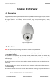
6 User Manual of IR Speed Dome Chapter 1 Overview 1.1 Description Integrated with the built-in pan/tilt unit, the medium speed dome features highly sensitive response and reliable performance. The speed dome can be adopted in various surveillance fields with its full-integral functions and features, such as corridor, large venue, meeting room, station, neighborhoods, etc. Figure 1-1 Appearance 1.2 Functions Note: The functions vary according to the different models of the speed dome.
7 User Manual of IR Speed Dome smooth transition from one preset scene to another. It also guarantees that masked area will not be revealed when the dome is moving to a preset. Presets A preset is a predefined image position. When the preset is called, the dome will automatically move to the defined position. The presets can be added, modified, deleted and called. Label Display The on-screen label of the preset title, PT display, zoom, and time can be displayed on the monitor.
8 User Manual of IR Speed Dome White Balance (WB) White balance can remove the unrealistic color casts. White balance is the white rendition function of the camera to adjust the color temperature according to the environment automatically. Patrol A patrol is a memorized series of pre-defined preset function. The scanning speed between two presets and the dwell time at the preset are programmable. Pattern A pattern is a memorized series of pan, tilt, zoom, and preset functions.
9 User Manual of IR Speed Dome Chapter 2 Getting Started 2.1 Power-up Action After the speed dome is power-on, it will perform a series of self-test actions. It runs the pan checking firstly, then the tilt checking and the camera checking at last. After the power-up actions, the system information will be displayed for 2 minutes on the live view screen as shown below. ADDRESS 0 COM FORMAT PROTOCOL 2400,8,1 SELF ADAPTIVE VERSION X.XX HARDVERSION BUILD DATE X.
10 User Manual of IR Speed Dome 2.2 Basic Operations You can operate the speed dome using a control device, including the control keyboard, DVR, DVS, etc. In this manual, accessing the speed dome via the web browser will be taken as an example. Panning and tilting: Click the direction buttons to control the pan and tilt movement of the speed dome. Zooming: Click the ZOOM+ and ZOOM- buttons to control the zooming. Focusing: Click the FOCUS+ and FOCUS- buttons to adjust the focus.
11 User Manual of IR Speed Dome Note: For Manchester code control protocol, the system-defined presets with special functions are shown as below: Table 1-1 System-defined Presets of Manchester Code Control Protocol Set Preset NO. 65 66 69 70 71 72 Function Remote reboot Access main menu Stop recording pattern Record Pattern 1 Record Pattern 2 Record Pattern 3 Call Preset NO. 67 70 71 72 Function Auto-flip Run Pattern 1 Run Pattern 2 Run Pattern 3 2.
12 User Manual of IR Speed Dome Chapter 3 Menu Operation Notes: 1. The operation interface of the different speed domes may differ. Please refer to the actual operation interface. 2. You can click the left and right direction buttons in the PTZ control panel via the IE browser of the DVR to enter the next page or return to the previous page of the submenu if more than one page is available.
13 User Manual of IR Speed Dome 5. For some other protocols, e.g. Manchester code control protocol, call preset 66 to access the menu. Please refer to Table 2-3 for details.
14 User Manual of IR Speed Dome SYS INFO ADDRESS 0 COM FORMAT PROTOCOL 2400,8,1 SELF ADAPTIVE VERSION 1.00 HARDVERSION 1.00 BUILD DATE 13 04 01 TEMPERATURE BACK 38℃ EXIT Figure 3-3 System Information Notes: Information on this menu cannot be edited. The temperature refers to the internal temperature of the speed dome. 3.2.2 Configuring System Parameters Purpose: You can check and also edit the system information of software address, baud rate, system time, etc.
15 User Manual of IR Speed Dome After you enable/disable the soft address, the speed dome will reboot automatically to activate the settings. To Set the Broadcast Address of the Speed Dome When the BROADCAST ADDRESS is set to ON, the control device with address 0 is capable of controlling all domes connected to it. Soft Baud Rate Settings If the SOFT BAUD ACTIVE is set as ON, the soft baud rate is the valid baud rate for the speed dome, with 2400, 4800, 9600 and 19200 selectable.
16 User Manual of IR Speed Dome Display Settings Purpose: You can enable or disable the on-screen display of PTZ movements, alarms, time, presets, zone, address, error rate, and fan/heat show, etc. Steps: (1) Move the cursor to DISPLAY SETTINGS using the direction buttons and click IRIS+ to enter. (2) Move the cursor to the target item and click IRIS+ and click up/down direction buttons to choose each display mode as ON or OFF, and define each display time as 2 seconds, 5 seconds or 10 seconds.
17 User Manual of IR Speed Dome IR PARAMETER IR SENSITIVITY IR PARAMETER MEDIUM FAN CONTROL TEMP N/M LED CURRENT 8 SWITCH DELAY(SEC) FAR LED CURRENT 8 HEAT CONTROL TEMP REFERENCE HEIGHT 4 IR CORRECTION N/A REFERENCE ZOOM 5 LED CONTROL BACK 8 CLOSE EXIT BACK EXIT Figure 3-7 IR Parameter Set the sensitivity of the IR LED. You can set the IR SENSITIVITY to HIGH, MEDIUM, or LOW. Set the electricity level of the IR LED.
18 User Manual of IR Speed Dome surveillance environments, which can be set as ON (normally on), OFF (normally off) or TEM (change according to the temperature). IR correction settings This parameter is to correct the focus problems caused by the IR light. You can turn IR CORRECTION ON or OFF. Note: IR correction settings vary according to the different camera models. Fan Parameter Configuration You can set the FAN CONTROL as TEMP (controlled by the temperature), ON or OFF.
19 User Manual of IR Speed Dome MAIN MENUS > DOME SETUP >CAMERA SETUP CAMERA CAMERA FOCUS AF BLC/WDR ZOOM LIMIT 22 BLC LEVEL ZOOM SPEED HIGH SLOW SHUTTER ON IRCUT FILTER AUTO OFF AUTO IRIS 10 SHUTTER 50 D/N LEVEL 1 GAIN SHARPNESS 8 EXPOSURE COMP BACK EXIT N/A BACK 7 EXIT CAMERA CAMERA WHITE BALANCE N/A AE MODE AUTO WIDE LIMIT 2.
20 User Manual of IR Speed Dome Purpose: Zoom limit is a user-defined limitation of the zoom amount (Zoom amount=optical zoom× digital zoom). If you set the zoom limit to the minimum value, the digital zoom will be invalid and the optical zoom will reach the maximum value; if you set the zoom limit smaller, the digital zoom will be enabled. Steps: (1) Move the cursor to ZOOM LIMIT using the direction buttons and click IRIS+ to enter.
21 User Manual of IR Speed Dome don’t support user-defined BLC level. Task 6: Configuring the iris, gain and shutter speed Set the AE Mode Purpose: AE mode defines the priority of iris, shutter and gain while the speed dome adjusting the brightness of the live view. You can change the mode on AE MODE submenu. AUTO: Auto iris, auto shutter and auto gain. The speed dome adjusts the values automatically responding to the lighting conditions. It is the default mode.
22 User Manual of IR Speed Dome the image is darker. (2) Slow shutter. Set SLOW SHUTTER as ON, the shutter speed can automatically slow down to extend exposure time under low lighting circumstances to obtain clearer image. Task 7: Configure exposure compensation. You can set the EXPOSURE COMP value from 0 to 14. The default value is 7. You can adjust this value to increase the brightness of the image. Task 8: Configure white balance.
23 User Manual of IR Speed Dome Note: The Chroma Suppress function is supported by certain camera model series. Saturation Saturation indicates the brightness of the color. The higher the saturation, the brighter the color is. Note: The saturation function is supported by certain camera model series. Contrast Contrast is the degree of difference between the darker and lighter parts of the image. Note: The contrast function is supported by certain camera model series.
24 User Manual of IR Speed Dome (1) Move the cursor to SET BLANK and click IRIS+ button to enter the editing mode as shown in the following figure. You can see a privacy mask on the live window. ADJUST BLANK POS FOCUS SHIFT STATUS SAVE: OPEN QUIT: CLOSE Figure 3-10 Set the Privacy Mask (2) You can see ADJUST BLANK POS message on the screen. Click the direction buttons to adjust the position of the privacy mask to the designed scene.
25 User Manual of IR Speed Dome MOTION MOTION AUTO FLIP ON PROPORTIONAL PAN ON PARK TIME PARK ACT 5 NONE SCAN SPEED 28 IMAGE FREEZE LIMIT STOP 4 OFF CLEAR STOPS ELEVATION SET ON OFF DOME SPEED BACK PRESET SPEED 6 EXIT BACK EXIT Figure 3-11 PTZ Configuration Auto-flip In manual tracking mode, when a target object goes directly beneath the speed dome, the speed dome automatically rotates 180 degrees horizontally for tracking.
26 User Manual of IR Speed Dome Purpose: You can define the speed of the dome movements. (1) DOME SPEED: The manual movement speed of the dome can be set from level 1 to 10. (2) SCAN SPEED: The scan speed defines the scan degree per second of pan scan, tilt scan, frame scan, random scan and panoramic scan. The scan speed is adjustable from level 1 to level 40 and the higher the level is, the faster the scan speed is. (3) PRESET SPEED: The speed of calling a preset can be set from level 1 to 8.
27 User Manual of IR Speed Dome PRESETS PRESET NUM 1 [UNDEFINED] PRESET PTZ CLEAR PRESET BACK EXIT Figure 3-12 Preset Configuration Menu 2. Choose the preset number: Move the cursor to PRESET NUM and click IRIS+ to enter. Click the up and down buttons to choose the preset number which needs to be edited. If the preset has been defined, the preset label will be listed under the number; if it has not been defined, you will see the information UNDEFINED under the number.
28 User Manual of IR Speed Dome PATROLS PATROL NUM 1 EDIT PATROL PREVIEW CLEAR PATH PATROL_D BACK 30S EXIT Figure 3-13 Patrol Configuration Menu 2. Choose the patrol number. Steps: (1) Move the cursor to PATROLS NUM and click IRIS+ to enter edit mode. (2) Click the up and down direction buttons to select the number of the patrol which is to be configured. (3) Click IRIS+ again to confirm the settings and exit edit mode of this column. Note: Up to 8 patrols can be configured. 3. Edit the patrol.
29 User Manual of IR Speed Dome 4. 5. 6. 7. to cancel and return to the previous menu. Preview the patrol. Move the cursor to PREVIEW and click IRIS+ to preview the current patrol. You can click IRS+ again to stop the preview. Call the defined patrol. You can call the special presets to call the defined patrol. E.g. call preset 35 to call patrol 1. Please refer to Section 2.3 to find the corresponding preset number for each patrol. Delete a patrol.
30 User Manual of IR Speed Dome Steps: (1) Move the cursor to EDIT PATTERN and click IRIS+ to enter edit mode. REMAIN MEMORY 100 DONE: OPEN QUIT: CLOSE Figure 3-16 Edit the Pattern (2) Click the PTZ control buttons and direction buttons to operate the speed dome to draw a movement path, including pan scan, tilt scan, zoom in, zoom out, etc. The speed dome can automatically memorize the path you operated as a pattern. (3) Click IRIS+ again to save the pattern and exit edit mode.
31 User Manual of IR Speed Dome MAIN MENU > DOME SETTINGS > TIME TASK TIME TASK TASK NUM 1 TASK STATE TASK ACTION ON NONE TASK TIME TASK PREVIEW TASK CLEAR BACK EXIT Figure 3-17 Time Task Configuration Menu 2. Choose the task number. Steps: (1) Move the cursor to TASK NUM and click IRIS+ to enter edit mode. (2) Click the up/down direction buttons to select the number of the task which is to be configured. (3) Click IRIS+ again to confirm the settings and exit the edit mode.
32 User Manual of IR Speed Dome Hour and the M refers to Minute. WEEK WHOLE WEEK START(H-M) 00 00 END(H-M) 00 00 DONE: OPEN QUIT: CLOSE Figure 3-18 Set the Task Time 6. Delete the task. Move the cursor to TASK CLEAR, click IRIS+ to delete the time and action of the current task, and click IRIS+ again to confirm the settings and exit. 3.4.6 Configuring Zone Purpose: A zone is a panning and tilting area defined by the left/right and up/down limit stops. You can configure the zones on ZONES submenu.
33 User Manual of IR Speed Dome Steps: (1) Move the cursor to EDIT ZONE and click IRIS+ button to enter the edit mode. (2) You can see SET LEFT LIMIT on the screen. Click the direction buttons to set the left limit stop. (3) Follow the prompts on the screen to set the right limit, up limit and down limit. (4) Click IRIS+ button to save the settings and exit. 4. Set the zone status and scan status. ZONE STATUS: The zone status just indicates the current status of the zone.
34 User Manual of IR Speed Dome DIAGNOSTICS DIAGNOSTICS HIGH TEMP HIGHEST TEMP LOW TEMP 0 PAN LOST 0 47°C TILT LOST 0 CAMERA LOST 0 0 LOWEST TEMP 23°C VIDEO LOSS 0 LOW VOLTAGE 0 POWER UP BACK 0 EXIT BACK EXIT Figure 3-21 Self-diagnostics Table 1-3 Descriptions of self-diagnostics information Item HIGH TEMP HIGHEST TEMP LOW TEMP LOWEST TEMP VIDEO LOSS LOW VOLTAGE Description The occurrence times of high temperature (higher than 65°C) The highest temperature The occurrence times of low
35 User Manual of IR Speed Dome 3. Click the left/right buttons to select the digit of the current password and click up/down or FOCUS+/- buttons to set the new value. 4. Click the right direction button to move the cursor to INPUT PW AGAIN and input the password again. 5. Click IRIS+ to save the new settings and exit. 6. Enter the START USING submenu and switch the status to ON and click IRIS+ to save.
36 User Manual of IR Speed Dome AE mode Exposure compensation White balance Auto-flip Proportional pan Park time Park act Scan speed Image freeze Limit stops Time show Zone show Address show Error rate show Zoom/PT/Preset show Auto 7 Auto On On 5 seconds None 28 Off Off Off On Off Off Off 3.5.3 Restoring Default Camera Settings Enter MAIN MENU > RESTORE CAMERA Click IRIS+ to restore the camera settings to the default value; or click IRIS- to exit.
37 User Manual of IR Speed Dome Appendix Appendix 1 Lightning & Surge Protection This product adopts TVS plate lightning protection technology to avoid damage caused by pulse signal that is below 3000W, like instantaneous lighting stroke, surging, etc. According to the actual outdoor situation, necessary protection measures must be taken, besides ensuring the electrical safety. The distance between signal transmission wires and High-voltage equipment or high-voltage cable is at least 50m.
38 User Manual of IR Speed Dome Appendix 2 RS485 Bus Connection General Property of RS485 Bus According to RS485 industry bus standard, RS485 is a half-duplex communication bus which has 120Ω characteristic impendence, the maximum load ability is 32 payloads (including controller device and controlled device). RS485 Bus Transmission Distance When using 0.56mm (24AWG) twisted-pair line, according to different baudrate, the maximum transmission distance theory table is shown as below: Table A-1 Max.
39 User Manual of IR Speed Dome faraway. At this time, the dome will be uncontrollable, or self-running, etc. 1# 6# 控 主 备 设 32# 15# Figure A-4 Star Shape Connection For such case, the best way is adding a RS485 distributor. This product can effectively change the star-shape connection to which satisfies the requirement of RS485 industry standard, in order to avoid those problems and improve the communication reliability. Show as figure 5.
40 User Manual of IR Speed Dome Problem dome can be controlled but not smoothly. Possible Reasons To Solve the Problem tightly. 2. RS485+ or RS485-wire is 2. Change a RS485 wire. broken. 3. The speed dome is too far away 3. Add a terminal resistor. from the remote control device. 4. Too many speed domes are 4. Add a RS485 distributor. connected. © Hikvision Digital Technology Co., Ltd. All Rights Reserved.
41 User Manual of IR Speed Dome Appendix 3 24VAC Wire Gauge & Transmission Distance The following table describes the recommended max. distance adopted for the certain wire gauge when the loss rate of 24VAC voltage is less than 10%. For the AC driven device, the maximum voltage loss rate is 10% allowable. For example, for a device with the rating power of 80VA which is installed at a distance of 35 feet (10m) away from the transformer, then 0.8000mm is required as the minimum wire gauge. 0.8000 1.000 1.
42 User Manual of IR Speed Dome Appendix 4 Table of Wire Gauge Standards Bare Wire Gauge(mm) 0.750 0.800 0.900 1.000 1.250 1.500 2.000 2.500 3.000 American Wire Gauge AWG 21 20 19 18 16 15 12 British Wire Gauge SWG 21 20 19 18 17 14 Cross-sectional Area of Bare Wire(mm2) 0.4417 0.5027 0.6362 0.7854 1.2266 1.7663 3.1420 4.9080 7.0683 © Hikvision Digital Technology Co., Ltd. All Rights Reserved.
/R &DOO ZZZ FFWYLUHODQG LH VKRS#FFWYLUHODQG LH