Digital servo amplifier SERVOSTAR™ 600 Assembly and Installation Instructions Edition 08/99
Previous versions : Edition 05/98 08/98 09/98 01/99 02/99 06/99 08/99 Remarks First edition a few corrections various minor corrections, parameter description removed, parameter setting for multi-axis systems and on/off switching behaviour added, Installation/Commissioning divided into two chapters 614 added, various minor corrections Interface relay for digital outputs (pages 26, 43) various corrections, cables and connectors removed, choke box added 24V tolerance, encoder wiring, ventilation VGA is a re
Kollmorgen 8.99 Contents Contents Drawing Page Contents . . . . . . . . . . . . . . . . . . . . . . . . . . . . . . . . . . . . . . . . . . . . . . . 3 Safety instructions . . . . . . . . . . . . . . . . . . . . . . . . . . . . . . . . . . . . . . . . 6 European directives and standards . . . . . . . . . . . . . . . . . . . . . . . . . . . . . 7 - / UL- conformance . . . . . . . . . . . . . . . . . . . . . . . . . . . . . . . . . . . . . . 7 Abbreviations and symbols . . . . . . . . . . . . . . . . . .
Contents 8.99 Kollmorgen Drawing Page III IV V VI 4 III.1 Interfaces Contents Power supply . . . . . . . . . . . . . . . . . . . . . . . . . . . . . . . . . . . . . . . . . . . . . . . . . . . . . . . . . . . . . . . . . . . . . . . . . . . . . . . . . . . . . 33 III.1.1 Mains supply connection (X0) . . . . . . . . . . . . . . . . . . . . . . . . . . . . . . . . . . . . . . . . . . . . . . . . . . . . . . . . . . . . . . . . . . 33 III.1.2 24V auxiliary supply (X4). . . . . . . . . . . . . . . .
Kollmorgen 8.
Safety instructions 8.99 Kollmorgen Safety Instructions l Only properly qualified personnel are permitted to perform activities such as transport, installation, commissioning and maintenance. Properly qualified persons are those who are familiar with the transport, assembly, installation, commissioning and operation of the product, and who have the appropriate qualifications for their job.
Kollmorgen 8.99 Directives and standards European directives and standa rds Servo amplifiers are components which are intended to be incorporated into electrical plants and machines for industrial use. When the servo amplifiers are built into machines or plants, the intended operation of the amplifier is forbidden until it has been established that the machine or plant fulfills the requirements of the EC Directive on Machines 89/392/EEC and the EC Directive on EMC (89/336/EEC).
Abbreviations / symbols Kollmorgen 8.99 Abbreviations used in this manual The abbreviations used in this manual are explained in the table below. Abbrev. Meaning AGND Analog ground Abbrev.
Kollmorgen General 8.99 I General I.1 About this manual This manual describes the digital servo amplifiers of the SERVOSTAR™ 600 series (standard version). You can find information about: l Technical data of the servo amplifier Chapter I l Assembly / installation Chapter II l Interfaces Chapter III l Commissioning the servo amplifier Chapter IV l Accessories Chapter V l Transport, storage, maintenance, disposal of the servo amp.
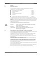
General I.3 Kollmorgen 8.99 - A.4.028.6/10 Nameplate The nameplate depicted below is attached to the side of the servo amplifer. The information described below is printed in the individual fields. Servo amplifier type Electrical supply Installed load I.4 Instrument description I.4.
Kollmorgen I.4.2 General 8.99 The digital servo amplifiers of the SERVOSTAR™ 600 family Standard version l 6 current ratings (1.
General I.4.4 8.
Kollmorgen I.5 8.99 - A.4.031.
General I.6 Kollmorgen 8.
Kollmorgen I.7 Technical data of the SERVOSTAR™ 600 series Rated data Rated supply voltage Rated installed load for S1 operation Rated DC-link voltage DIM V~ kVA V= Arms Rated output current (rms value, ± 3%) Peak output current (max. ca. 5s, ± 3%) Clock frequency of the output stage Technical data for regen circuit Overvoltage protection threshold Form factor of the output current (at rated data and min.
General I.7.2 8.99 Kollmorgen Permissible ambient conditions, ventilation, mounting position Storage temperature/humidity, storage duration Transport temperature / humidity Supply voltage tolerances Input power Aux. power supply Ambient temperature in operation Humidity in operation Site altitude Pollution level Enclosure protection Mounting position Ventilation SERVOSTAR™ 601-620 ð p.59 ð p.59 min 3x230V-10% AC / max 3x 480V+10% , 50 ...
Kollmorgen I.8 8.99 - A.4.031.3/01, 1/35 General Grounding system AGND — ground for analog inputs/outputs, internal analog ground DGND — ground for digital inputs/outputs, optically isolated XGND — ground for external 24V aux. voltage, optically and inductively isolated PGND — ground for encoder emulation, RS232, CAN, optically isolated The potential isolation is shown in the block diagram (ð p.13). I.9 Control for motor-holding brake A 24V / max.
General I.10 Kollmorgen 8.99 Regen circuit During braking with the aid of the motor, energy is fed back to the servo amplifier. This energy is converted into heat in the regen resistor. The regen circuit (thresholds) are adjusted to the supply voltage with the help of the setup software. Our applications department can help you with the calculation of the regen power which is required. A description of the interface can be found on page 34 .
Kollmorgen I.11 8.99 - A.4.031.3/6 General Switch-on and switch-off behaviour The diagram below illustrates the correct functional sequence for switching the servo amplifier on and off. If you are using the digital output function MAINS-BTB/RTO, you can find a diagram which is valid for this case in the “Setup Software” manual. DC-link I.11.1 Stop function to EN 60204 (VDE 0113) If a fault occurs (ð p.52) the output stage of the servo amplifier is switched off and the BTB/RTO contact is opened.
General I.11.2 8.99 Kollmorgen Emergency Stop strategies The Emergency Stop function is defined in EN 60204 (VDE 0113), Para. 9.2.5.4. Implementation of the Emergency Stop function : You can find wiring recommendations in our application note “Stop and Emergency Stop functions with SERVOSTAR™ 600” Category 0: The controller is switched to “disable”, the electrical supply (400VAC) is disconnected. The motor leads are disconnected by a changeover switch (contactor, e.g.
Kollmorgen 8.99 II Installation II.1 Important instructions Installation l Protect the servo amplifier from impermissible stresses. In particular, do not let any components become bent or any insulation distances altered during transport and handling. Avoid contact with electronic components and contacts. l Check the combination of servo amplifier and motor. Compare the rated voltage and current of the units.
Installation II.2 Kollmorgen 8.99 - A.4.031.
Kollmorgen II.2.1 8.99 - A.4.031.
Installation II.3 Kollmorgen 8.99 Wiring Only professional staff who are qualified in electrical engineering are allowed to install the servo amplifier. The installation procedure is described as an example. A different procedure may be sensible or necessary, depending on the application of the equipment. We provide further know-how through training courses (on request). Caution ! Only install and wire up the equipment when it is not live, i.e.
Kollmorgen 8.99 Installation The following notes should assist you to carry out the installation in a sensible sequence, without overlooking anything important. Site In a closed switchgear cabinet. Observe page 16 . The site must be free from conductive or corrosive materials. For the mounting position in the cabinet ð p.22 Ventilation Check that the ventilation of the servo amplifier is unimpeded and keep within the permitted ambient temperature ð p.16 .
Installation II.3.1 8.99 - A.4.031.1/2 Kollmorgen Connection diagram for SERVOSTAR™ 600 SERVOSTAR™ 600 ð p.37 ð p.36 ð p.40 ð p.35 ð p.34 ð p.38 ð p.39 ð p.34 ð p.41 ð p.42 ð p.46 ð p.33 ð p.45 ð p.44 ð p.33 ð p.43 ð p.
Kollmorgen 8.99 - A.4.031.1/19 II.3.
Installation II.3.3 28 8.99 - A.4.031.
Kollmorgen II.3.4 8.99 - A.4.029.4/25 Installation Notes on connection techniques Please consider our application note “Cables and connectors” II.3.4.1 Shielding connection to the front panel Remove the outer covering of the cable and the shielding braid from the cores for the required length. Secure the cores with a cable tie. Remove the outer covering of the cable over a length of about 30mm, without damaging the shielding braid.
Installation II.3.4.2 Kollmorgen 8.99 - A.4.029.4/25 Technical data for connecting cables Further information on the chemical, mechanical and electrical characteristics of the cables can be obtained from our applications department. Insulation material Sheathing PUR (polyurethane, code 11Y) Core insulation PETP (polyesteraphtalate, code 12Y) Capacitance Motor cable less than 150 pF/m RES-cable less than 120 pF/m Technical data — The brackets in the cable designation indicate the shielding.
Kollmorgen 8.99 II.4 Setup software II.4.1 General Installation This chapter describes the installation of the setup software for the SERVOSTAR™ 600 digital servo amplifiers. We offer training and familiarisation courses on request. II.4.1.1 Use as directed The setup software is intended to be used for setting up and storing the operating parameters for the SERVOSTAR™ 600 series of servo amplifiers.
Installation II.4.1.3 8.99 Kollmorgen Hardware requirements The PC interface (X6, RS232) of the servo amplifier is connected to the serial interface of the PC by a null-modem cable (not a null-modem link cable !) (ð p.43). Connect / disconnect the interface cable only when the supply is switched off for both the PC and the servo amplifier. The interface in the servo amplifier is electrically isolated by an optocoupler, and is at the same potential as the CANopen interface.
Kollmorgen III 8.99 - A.4.031.1/21,25 Interfaces Interfaces All important interfaces are shown in this Chapter. The precise location of the connectors and terminals can be seen on page 28. III.1 Power supply III.1.1 Mains supply connection (X0) — — Directly to earthed 3~ supply, 230V-10% — 480V+10%, 50 — 60 Hz, integrated filter Fusing (e.g. fusible cut-outs) provided by the user ð p.15 SERVOSTAR™ 600 III.1.2 24V auxiliary supply (X4) — Electrically isolated, external 24V DC supply, e.g.
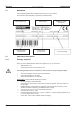
Interfaces III.2 8.99 - A.4.031.1/17,18 Kollmorgen Motor connection with brake (X9) Lead length £ 25m SERVOSTAR™ 600 Lead length >25m For lead lengths above 25m the choke box 3YL-20 must be wired into the motor lead, close to the amplifier. SERVOSTAR™ 600 III.3 External regen resistor (X8) Remove the plug-in link between the terminals X8/1 (-R B) and X8/2 (+Rbint ).
Kollmorgen 8.99 - A.4.031.1/26 III.4 Feedback III.4.1 Resolver connection (X2) Interfaces The motors of the 6SM or GOLDLINE™ BH series have 2-pole hollow-shaft resolvers built in as a standard. It is possible to connect 2, 4 or 6-pole resolvers to the SERVOSTAR™ 600. If lead lengths of more than 100m are planned, please contact our application department. The thermostat contact in the motor is connected via the resolver cable to the SERVOSTAR™ 600 and evaluated there.
Interfaces III.4.2 8.99 - A.4.031.1/27 Kollmorgen Encoder (X1) As an option, the 6SM series of motors can be fitted with a single-turn or multiturn sine-cosine encoder. This encoder is used by the SERVOSTAR™ 600 as a feedback device for drive tasks which require highly precise positioning or extremely smooth running. If lead lengths of more than 100m are planned, please consult our applications department.
Kollmorgen 8.99 - A.4.031.1/23 III.5 Control signals, monitor signals III.5.1 Analog setpoint inputs (X3) Interfaces The servo amplifier is equipped with two differential inputs for analog setpoints which are freely programmable (with the aid of the macro-language, consult our applications department). AGND (X3/1) must always be joined to the CNC-GND of the controls as a ground reference. Technical characteristics — — — — — Differential-input voltage max. ± 10 V Resolution 1.
Interfaces III.5.2 8.99 - A.4.031.1/24 Kollmorgen Digital setpoint inputs (X3) All digital inputs are electrically isolated through optocouplers. Technical characteristics — — — Reference ground is digital-GND (DGND, terminal X3/18) The logic is dimensioned for +24V / 7mA (PLC-compatible) H-level of +12 — 30V / 7mA, L-level of 0 — 7V / 0 mA SERVOSTAR™ 600 ENABLE input The output stage of the servo amplifier is activated by the enable signal (terminal X3/15, input 24V, active-high).
Kollmorgen III.5.3 8.99 - A.4.031.1/20 Interfaces Digital control outputs (X3) Technical characteristics — — — Reference ground is digital-GND (DGND, terminal X3/18) All digital outputs are floating DIGITAL-OUT1 and 2 : Open-collector, max. 30V DC, 10 mA BTB/RTO : Relay output, max. 30V DC or 42V AC, 0.5A SERVOSTAR™ 600 Ready-to-operate contact BTB/RTO Operational readiness (terminals X3/2 and X3/3 ) is signalled by a floating relay contact.
Interfaces III.5.4 8.99 - A.4.031.1/22 Kollmorgen Monitor outputs (X3) Technical characteristics — — — — Reference ground is analog-GND (AGND, terminal X3/1 and X3/10) Output resistance : 2.2kW Output voltage ±10V Resolution : 10 bit.
Kollmorgen 8.99 - A.4.031.1/11 III.6 Encoder emulations III.6.1 Incremental-encoder interface (X5) Interfaces The incremental-encoder interface is part of the package supplied. Select the encoder function ROD (screen page “Encoder”). In the servo amplifier, the position of the motor shaft is calculated from the cyclic-absolute signals of the resolver or encoder. Incremental-encoder compatible pulses are generated from this information.
Interfaces III.6.2 8.99 - A.4.031.1/12 Kollmorgen SSI-Interface (X5) The SSI interface (synchronous serial absolute-encoder emulation) is part of the delivered package. Select the encoder function SSI (screeen page “Encoder”). In the servo amplifier, the position of the motor shaft is calculated from the cyclic-absolute signals of the resolver or encoder. A position output is generated from this information, compatible with the data format of normal commercial SSI absolute encoders.
Kollmorgen III.7 8.99 - A.4.031.1/13,14 Interfaces RS232 interface, PC connection (X6) The setting of the operating, position control, and motion-block parameters can be carried out with an ordinary commercial PC. Connect the PC interface (X6) of the servo amplifier while the supply to the equipment is switched off via a normal commercial 3-core null-modem cable to a serial interface on the PC.
Interfaces III.8 8.99 - A.4.031.1/15, 1/36 Kollmorgen CANopen Interface (X6) The interface for connection to the CAN bus (default 500 kBaud). The integrated profile is based on the communication profile CANopen DS301 and the drive profile DSP402. The following functions are available in connection with the integrated position controller: Jogging with variable speed, reference traverse (zeroing), start motion task, start direct task, digital setpoint provision, data transmission functions and many others.
Kollmorgen III.9 8.99 - A.4.031.1/10,3/2 Interfaces Interface for stepper-motor controls (X5) This interface can be used to connect the servo amplifier to a third-party stepper-motor controller. The parameters for the servo amplifier are set up with the aid of the setup software. The number of steps can be adjusted, so that the servo amplifier can be adjusted to the pulse-direction signals of any stepper-motor controller. Various monitoring signals can be output.
Interfaces III.10 Kollmorgen 8.99 - A.4.031.1/16,3/2 Interface for master-slave operation, encoder input (X5) This interface can be used to link several SERVOSTAR™ 600 amplifiers together in master-slave operation. Up to 16 slave amplifiers can be controlled by the master via the encoder output. The parameters for the slave amplifiers are set up with the aid of the setup software. The resolution (no. of pulses/turn) can be adjusted. The analog setpoint inputs are out of action.
Kollmorgen 8.99 IV Commissioning IV.1 Important notes Commissioning Only professional personnel with extensive knowledge in the fields of electrical/ drive technology are allowed to commission the servo amplifier. The procedure for commissioning is described as an example. Depending on the application, a different procedure may be sensible or necessary. In multi-axis systems, commission each servo amplifier individually.
Commissioning 8.99 Kollmorgen The following instructions should help you to carry out the commissioning in a sensible order, without any hazards to people or machinery. Check installation Inhibit Enable signal 0V on terminal X3/15 (Enable) Switch on 24V auxiliary voltage 24V DC on terminal X4/1, ground on terminal X4/3 After the initialisation procedure (about 0.5 sec.) the status is shown in the LED display ( ð p.
Kollmorgen IV.2 Commissioning 8.99 - A.4.031.4/37 Parameter setting A default parameter set is loaded into your servo amplifier by the manufacturer. This contains valid and safe parameters for the current and speed controllers. A database for motor parameters is stored in the servo amplifier. During commissioning you must select the data set for the motor that is connected and store it in the servo amplifier. For most applications these settings will already provide good control loop characteristics.
Commissioning IV.2.2 Kollmorgen 8.99 - A.4.031.3/4 Key operation / LED display In this chapter the two possible operation menus and the use of the keys in the front panel are shown. Normally, the SERVOSTAR™ 600 only places the standard menu at your disposal. If you want to attend the amplifier via the detailed menu, you must keep the right key pressed while switching on the 24V-supply. IV.2.2.1 Key operation The two keys can be used to perform the following functions: U Key symbol U U U IV.2.2.
Kollmorgen IV.2.2.3 Commissioning 8.99 - A.4.031.3/3 Extended menu structure p.49 p.
Commissioning IV.3 8.99 Kollmorgen Error messages Errors which occur are shown in coded form by an error number in the LED display on the front panel. All error messages result in the BTB/RTO contact being opened, and the output stage of the amplifier being switched off (motor looses all torque). If a motor-holding brake is installed, it will be activated.
Kollmorgen IV.4 8.99 Commissioning Warning messages Faults which occur, but which do not cause a switch-off of the amplifier output stage (BTB/RTO contact remains closed) , are indicated in the LED display on the front panel by a coded warning number.
Commissioning 8.99 Kollmorgen This page has been deliberately left blank.
Kollmorgen 8.99 - A.4.012.4/33 V Accessories V.
Accessories V.2 56 8.99 - A.4.947.
Kollmorgen V.3 8.99- A.4.030.4/10 Accessories Motor choke box 3YL-20 Technical data: Nom. data Rated corrent Frequency Inductance Sym I0rms f max L DIM A kHz mH 3 YL-20 Max. 3 x 20 8.3 1.
Accessories 8.99 Kollmorgen This page has been deliberately left blank.
Kollmorgen 8.99 VI Appendix VI.1 Transport, storage, maintenance, disposal Appendix Transport : — only by qualified personnel — only in the manufacturer’s original recyclable packaging — avoid shocks — temperature –25 to +70°C, max. 20°C / hour rate of change — humidity max. 95% relative humidity, no condensation — the servo amplifiers contain electrostatically sensitive components which can — be damaged by incorrect handling — Discharge yourself before touching the servo amplifier.
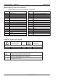
Appendix VI.2 Kollmorgen 8.99 Removing faults The table below should be regarded as a “First-aid” box. Depending on the conditions in your installation, there may be a wide variety of reasons for the fault. In multi-axis systems there may be further hidden causes of a fault. Our applications department can give you further assistance with problems.
Kollmorgen Fault message: feedback unit message: internal temperature Message: motor temperature Appendix 8.
Appendix VI.3 C D Kollmorgen 8.
Kollmorgen P R S T Z Appendix 8.
Appendix 8.99 Kollmorgen This page has been deliberately left blank.
Kollmorgen VI.4 Index ! 24V supply 20A. . . . . . . . . . . . . . . . . . . . . 55 24Vaux. supply, interface . . . . . . . . . . . 33 A abbreviations . . . . . . . . . . . . . . . . . . 8 AGND . . . . . . . . . . . . . . . . . . . . . 17 ambient temperature . . . . . . . . . . . . . . 16 assembly . . . . . . . . . . . . . . . . . . . . 22 Assignment . . . . . . . . . . . . . . . . . . . 30 B Baudrate . . . . . . . . . . . . . . . . . . . . 49 brake . . . . . . . . . . . . . . . . . . . . . .
Ve r t r ie b u n d S er vi ce / S al es a n d S e rv i c e / A g e n c e e t S e r v i c e s Bund es repu b lik De uts c hl a n d / Ge rma ny / A llemag n e Seidel Servo Drives GmbH Verkaufsniederlassung Nord Heinrich-Albertz- Str. 40 D-29221 Celle Tel.: +49(0)5141 - 98 10 40 Fax: +49(0)5141 - 98 10 41 Seidel Servo Drives GmbH Verkaufsniederlassung West Wacholderstr. 40-42 D-40489 Düsseldorf Tel.