SERVOSTAR 640...670 Digital Servo Amplifier S600 Instructions Manual Edition 02/2015 Translation of the original manual. Valid for Hardware Revision 02.20 Keep all manuals as a product component during the life span of the product. Pass all manuals to future users / owners of the product. File sr640_e.
Previous versions : Edition 07/1999 11/1999 12/1999 10/2000 05/2001 01/2002 06/2002 02/2006 09/2006 04/2007 07/2007 06/2008 08/2008 07/2010 12/2010 12/2014 02/2015 Remarks First edition technical data, encoder connection diagram encoder cable length Dimensions mains filter, setup software on CD-ROM only, wiring diagrams electr.
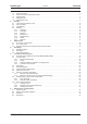
Kollmorgen 02/2015 Contents Page 1 General 1.1 1.2 1.3 1.4 1.5 2 About this manual . . . . . . . . . . . . . . . . . . . . . . . . . . . . . . . . . . . . . . . . . . . . . . . . . . . . . . . . . . . . . . . . . . . . . . . Hints for the online edition (PDF format) . . . . . . . . . . . . . . . . . . . . . . . . . . . . . . . . . . . . . . . . . . . . . . . . . . . . . . Symbols used. . . . . . . . . . . . . . . . . . . . . . . . . . . . . . . . . . . . . . . . . . . . . . . . . . . . . . . . . . . .
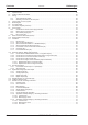
Contents 02/2015 Kollmorgen Page 7 Electrical Installation 7.1 7.2 7.3 Important notes . . . . . . . . . . . . . . . . . . . . . . . . . . . . . . . . . . . . . . . . . . . . . . . . . . . . . . . . . . . . . . . . . . . . . . . . Guide to electrical installation. . . . . . . . . . . . . . . . . . . . . . . . . . . . . . . . . . . . . . . . . . . . . . . . . . . . . . . . . . . . . . Wiring. . . . . . . . . . . . . . . . . . . . . . . . . . . . . . . . . . . . . . . . . . . . . . . . . . . . . . . . .
Kollmorgen 02/2015 Contents Page 8 Setup 8.1 8.2 Important notes . . . . . . . . . . . . . . . . . . . . . . . . . . . . . . . . . . . . . . . . . . . . . . . . . . . . . . . . . . . . . . . . . . . . . . . . Setup software . . . . . . . . . . . . . . . . . . . . . . . . . . . . . . . . . . . . . . . . . . . . . . . . . . . . . . . . . . . . . . . . . . . . . . . . . 8.2.1 General . . . . . . . . . . . . . . . . . . . . . . . . . . . . . . . . . . . . . . . . . . . . . . . . . . . . . . . . . . . . . .
Contents 02/2015 Kollmorgen Page 9.6 Expansion card -ETHERCAT- . . . . . . . . . . . . . . . . . . . . . . . . . . . . . . . . . . . . . . . . . . . . . . . . . . . . . . . . . . . . 9.6.1 Front view . . . . . . . . . . . . . . . . . . . . . . . . . . . . . . . . . . . . . . . . . . . . . . . . . . . . . . . . . . . . . . . . . . . . . . 9.6.2 LEDs . . . . . . . . . . . . . . . . . . . . . . . . . . . . . . . . . . . . . . . . . . . . . . . . . . . . . . . . . . . . . . . . . . . . . . . . . . 9.6.
Kollmorgen 02/2015 1 General 1.1 About this manual General This manual describes the digital servo amplifiers of the SERVOSTAR 640/670 series (standard version). A more detailed description of the expansion cards which are currently available and the digital connection to automation systems can be found on the accompanying CD-ROM in Acrobat-Reader format (system requirements: WINDOWS with Internet browser, Acrobat Reader) in several language versions.
General 1.
Kollmorgen 1.5 02/2015 General Abbreviations used The abbreviations used in this manual are explained in the table below.
Safety 2 02/2015 Kollmorgen Safety This section helps you to recognize and avoid dangers to people and objects. 2.1 You should pay attention to this Specialist staff required! Only properly qualified personnel are permitted to perform such tasks as transport, assembly, setup and maintenance.
Kollmorgen 02/2015 Safety Automatic restart The drive might restart automatically after power on, voltage dip or interruption of the supply voltage, depending on the parameter setting. Risk of death or serious injury for humans working in the machine. If the parameter AENA is set to 1, then place a warning sign to the machine (Warning: Automatic Restart at Power On) and ensure, that power on is not possible, while humans are in a dangerous zone of the machine.
Safety 2.2 02/2015 Kollmorgen Use as directed l The servo amplifiers are components which are built into electrical equipment or machines, and can only be used as integral components of such equipment. l The manufacturer of the machine must generate a risk assessment for the machine, and take appropriate measures to ensure that unforeseen movements cannot cause injury or damage to any person or property. l The SERVOSTAR 640/670 family of servo amplifiers (overvoltage category III acc.
Kollmorgen 02/2015 2.4 Handling 2.4.1 Transport Safety l Only by qualified personnel in the manufacturer’s original recyclable packaging l Avoid shocks l Temperature l Humidity l If the packaging is damaged, check the unit for visible damage. In this case, inform the shipper and the manufacturer. –25 to +70°C (-13...158°F), max. 20K/hr rate of change max.
Safety 2.4.5 02/2015 Kollmorgen Disassembling Observe the sequence below, if a servo amplifier has to be disassembled (e.g. for replacement). 1. Electrical disconnection a. b. c. Switch off the main switch of the switchgear cabinet and the fuses that supply the system. Warning: Contacts can still have dangerous voltages present up to five minutes after switching off mains voltage.
Kollmorgen 3 Approvals 02/2015 Approvals Certificates can be found in our Product WIKI on page Approvals. 3.1 UL and cUL- Conformance This servo amplifier is listed under UL file number E217428. UL (cUL)-certified servo amplifiers (Underwriters Laboratories Inc.) fulfill the relevant U.S. and Canadian standard (in this case UL 840 and UL 508C).
Approvals 3.2 02/2015 Kollmorgen EC - conformance The servo amplifiers have been tested in a defined configuration, using the system components that are described in this documentation. Any divergence from the configuration and installation described in this documentation means that you will be responsible for carrying out new measurements to ensure conformance with regulatory requirements.
Kollmorgen Package 02/2015 4 Package 4.1 Package supplied When you order a SERVOSTAR 640/670 series amplifier (order codes ð p.111), you will receive: — — SERVOSTAR 640/670 mating connectors X3, X4 The mating SubD connectors are not part of the package! — — — Assembly and Installation Instructions (product manual) Online documentation on CD-ROM Setup software DRIVE.EXE on CD-ROM Accessories: (must be ordered separately; description see accessories manual) — — — — — — — — — 4.
Package 4.3 02/2015 Kollmorgen Part number scheme S 6 4 0 0 1 - S E* Family S6 S600 Expansions NA no expansion DN DeviceNet PB PROFIBUS SE SERCOS SN SynqNet EC ETHERCAT IO I/O-Expansion Current rating 40 40A rms 70 70A rms Voltage rating 0 230...480V electr. option 1 AS * additional coding defines customer specific specials.
Kollmorgen 02/2015 Technical description 5 Technical description 5.1 The digital servo amplifiers of the series SERVOSTAR 640/670 Standard version l 2 current ratings (40 A, 70 A) l Wide range of rated voltage (3x208V –10% to 3x480V +10%) l Overvoltage category III acc.
Technical description 02/2015 Kollmorgen Operation and parameter setting l With our user-friendly software for setup through the serial interface of a PC l Direct operation by means of two keys on the servo amplifier and a 3-character LED display for status display in case of no PC available l Fully programmable via RS232 interface Completely digital control l Digital current controller (space vector pulse-width modulation, 62.5 µs) l Freely programmable digital speed controller (62.
Kollmorgen 5.2 Technical description 02/2015 Technical data Rated data Rated-supply voltage (grounded system) Rated installed load for S1 operation Rated DC bus link voltage Rated output current (rms value, ± 3%) at 230V at 400V at 480V Peak output current (max. ca. 5s, ± 3%) at 230V at 400V at 480V Clock frequency of the output stage Technical data of the brake circuit Overvoltage protection threshold Form factor of the output current (at rated data and min.
Technical description 5.2.1 Recommended torques Connector X3, X4 X10 X0 5.2.2 Kollmorgen 02/2015 Recommended torque 0.3 Nm (2.25 in lb) 0,3 Nm (2.25 in lb) 6...8 Nm (45... 60 in lb) Fusing Tips and detailed information can be found in the Product-Wiki (follow the link on www.wiki-kollmorgen.eu) on page "Fuses".
Kollmorgen 5.2.4 02/2015 Technical description Conductor cross-sections Observe the technical data for connection cables ð p. 38. Following EN 60204 (for AWG: table 310-16 of the NEC 60°C or 75°C column), we recommend for single-axis systems: 25 mm² (2 awg), shielded between filter and amplifier, 600V, 80°C (176°F) DC bus link 25 mm² (2 awg), shielded for lengths > 20 cm, 600V, 80°C (176°F) ð p.
Technical description 5.5 02/2015 Kollmorgen Control for motor holding brake A 24 V / max. 3 A holding brake in the motor can be controlled directly by the servo amplifier. CAUTION This function does not ensure functional safety! Danger by falling load (in case of suspended load, vertical axes). An additional mechanical brake is required for funktional safety, which must be safely operated. The brake only works with sufficient voltage level (ð p.22).
Kollmorgen 5.6 02/2015 Technical description Electrical brake circuit During braking with the aid of the motor, energy is fed back to the servo amplifier. This energy is converted into heat in the brake resistor (ð p. 112). The brake resistor is switched into circuit by the brake circuit. The brake circuit (thresholds) are adjusted to the supply voltage with the help of the setup software. Our customer service can help you with the calculation of the brake power which is required.
Technical description 5.7 02/2015 Kollmorgen Switch-on and switch-off behavior This chapter describes the switch-on and switch-off behavior of the SERVOSTAR 6xx and the steps required to achieve operational stopping or emergency stop behavior that complies with standards. The servo amplifier’s 24 V supply must remain constant. The ASCII commands ACTFAULT (error response, also depends on the specific error, see ERRCODE) and STOPMODE (Enable signal response) dictate how the drive will behave.
Kollmorgen 5.7.1 02/2015 Technical description Behavior in standard operation The behavior of the servo amplifier always depends on the current setting of a number of different parameters (e.g., ACTFAULT, VBUSMIN, VELO, STOPMODE, etc.; see online help). The diagram below illustrates the correct functional sequence for switching the servo amplifier on and off.
Technical description 5.7.2 02/2015 Kollmorgen Behavior in the event of an error (with standard setting) The behavior of the servo amplifier always depends on the current setting of a number of different parameters (e.g., ACTFAULT, VBUSMIN, VELO, STOPMODE, etc.; see online help ). The diagram shows the startup procedure and the procedure that the internal control system follows in the event of one or more electrical supply phases failing, assuming that the standard parameter settings apply.
Kollmorgen 5.8 02/2015 Technical description Stop/Emergency Stop Function to EN 60204 With the restart lock –AS- (see page 67 onwards) the drive can be secured on standstill (torque-free) using its internal electronics so that even when power is being supplied, the drive shaft is protected against unintentional restart. The parameters “STOPMODE” and “ACTFAULT” must be set to 1 in order to implement the stop categories.
Technical description 5.8.2 02/2015 Kollmorgen Emergency Stop: Standards The emergency Stop function is used for the fastest possible shut-down of the machine in a dangerous situation. The Emergency Stop function can be triggered by the actions of a single person. It must be fully functional and available at all times. The user must not have to work out how to operate this mechanism. The Emergency Stop function is defined by EN 60204.
Kollmorgen 02/2015 5.9 Shock-hazard protection 5.9.1 Leakage current Technical description Leakage current via the PE conductor results from the combination of equipment and cable leakage currents. The leakage current frequency pattern comprises a number of frequencies, whereby the residual-current circuit breakers definitively evaluate the 50Hz current. For this reason, the leakage current cannot be measured using a conventional multimeter.
Mechanical Installation 02/2015 6 Mechanical Installation 6.1 Important notes Kollmorgen WARNING There is a danger of electrical shock by high EMC level which could result in injury, if the servo amplifier (or the motor) is not properly EMC-grounded. Do not use painted (i.e. non-conductive) mounting plates. In unfavourable circumstances, use copper mesh tape between the earthing bolts and earth potential to deflect currents. Protect the servo amplifier from impermissible stresses.
Kollmorgen 6.
Mechanical Installation 6.
Kollmorgen 02/2015 7 Electrical Installation 7.1 Important notes Electrical Installation WARNING There is a danger of electrical arcing when disconnecting connectors, because capacitors can still have dangerous voltages present up to five minutes after switching off the supply power. Risk of burns and blinding. The contacts become damaged. Never undo any electrical connections to the servo amplifier while it is live.
Electrical Installation 7.2 02/2015 Kollmorgen Guide to electrical installation The following notes should assist you to carry out the electrical installation in a sensible sequence, without overlooking anything important. Cable selection Grounding Shielding Wiring Final check 36 Select cables according to EN 60204 (ð p. 23) EMC-compliant (EMI) shielding and grounding (ð p. 42) Earth (ground) the mounting plate, motor housing and CNC-GND of the controls.
Kollmorgen 7.3 Electrical Installation 02/2015 Wiring The installation procedure is described as an example. A different procedure may be sensible or necessary, depending on the application of the equipment. We provide further know-how through training courses (on request). DANGER Severe electric shock injuries or death may be sustained when working on installations which have not been disconnected.
Electrical Installation 7.3.1 02/2015 Kollmorgen Technical data for cables Further information on the chemical, mechanical and electrical characteristics of the cables can be obtained from out customer service . Observe the restrictions in the chapter "Conductor cross-sections" on page 23. To operate the amplifier with the max. permitted cable length, you must use cable material which meets the requirements on the capacity given below.
Kollmorgen 7.4 Electrical Installation 02/2015 Components of a servo system SERVOSTAR 640/670 PC Control / PLC Restart lock -AS- 24V-power supply Mains filter Fuses Mains choke Brake resistor Drive contactor Fuses Motor Terminals Cables drawn bold are shielded. Electrical ground is drawn with dash-dotted lines. The required accessories are described in our accessories manual.
Electrical Installation 7.5 02/2015 Kollmorgen Block diagram The block diagram below is just an overview.
Kollmorgen 02/2015 Electrical Installation SERVOSTAR 640/670 Instructions Manual 41 7.
Electrical Installation 7.7 Kollmorgen 02/2015 Connection diagram (overview) Reference Safety Instructions (ð p.10) and Use As Directed (ð p.12) ! SERVOSTAR 640/670 ð p.61 ð p.48ff ð p.62 ð p.47 ð p.45 ð p.63 ð p.44 ð p.64 ð p.45 ð p.44 ð p.67 ð p.59 ð p.60 ð p.54 ð p.57 ð ð p.65 ð p.95 ð p.98 ð p.
Kollmorgen 02/2015 7.8 Power supply 7.8.1 Connection to various mains supply networks Electrical Installation This page illustrates all the possible connection variations for different electrical supply networks. An isolating transformer is always required for 400...480V mains networks without earth (ground) and for networks with asymmetrical earth (ground). 208V with 60Hz only 230...
Electrical Installation 7.8.2 02/2015 Kollmorgen Mains supply connection (X0) — — EMI filter and mains choke (required) provided by the user Fusing (e.g. fusible cut-outs) provided by the user ð p. 22 SERVOSTAR 640/670 7.8.3 24V auxiliary supply (X4) — — — Electrically isolated, external 24VDC supply, e.g. with insulating transformer Required current rating ð p. 21 Integrated EMI filter for the 24V auxiliary supply SERVOSTAR 640/670 7.8.
Kollmorgen 7.9 02/2015 Electrical Installation Motor connection with brake (X0, X4) Cable cross section see motor documentation. SERVOSTAR 640/670 7.
Electrical Installation 7.11 Kollmorgen 02/2015 Feedback Every closed servo system will normally require at least one feedback device for sending actual values from the motor to the servo drive. Depending on the type of feedback device used, information will be fed back to the servo amplifier using digital or analog means.
Kollmorgen 7.11.1 02/2015 Electrical Installation Resolver (X2) Connection of a Resolver (2 to 36-poles) as a feedback system. The thermal control in the motor is connected via the resolver cable to the SERVOSTAR and evaluated there. If cable lengths of more than 100 m are planned, please contact our customer service . FBTYPE 0, 3 SERVOSTAR 640/670 The pin assignment shown on the encoder side relates to the Kollmorgen motors.
Electrical Installation 7.11.2 02/2015 Kollmorgen Sine encoder with BISS (X1) Wiring of a single-turn or multi-turn sine-cosine encoder with BISS interface as a feedback system (firmware revision from 6.68). During start-up of the servo amplifier the parameters stored in the encoder eeprom are uploaded, after that phase only the sine/cosine signals are used. The thermal control in the motor is connected via the encoder cable to X1 and evaluated there.
Kollmorgen 7.11.3 Electrical Installation 02/2015 Sine Encoder with EnDat 2.1 or HIPERFACE (X1) Connection of a single-turn or multiturn sine-cosine encoder. Preferred types are ECN1313 and EQN1325. The thermal control in the motor is connected via the resolver cable to the SERVOSTAR and evaluated there. All signals are connected using our pre-assembled encoder connection cable. If cable lengths of more than 50 m are planned, please consult our customer service.
Electrical Installation 7.11.4 02/2015 Kollmorgen Sine Encoder without data channel (X1) Connection of a sine-cosine encoder without data channel as feedback unit. Every time the 24V auxiliary voltage is switched on, the amplifier needs start-up information for the position controller (parameter value MPHASE). Depending on the feedback type either wake&shake is executed or the value for MPHASE is read out of the amplifier's EEPROM.
Kollmorgen 7.11.5 02/2015 Electrical Installation Incremental or sine encoder with hall sensors (X1) Feedback devices (incremental or sine-cosine), which don't deliver an absolute information for commutation, can be used as complete feedback system combined with an additional Hall encoder. All signals are connected to X1. If cable lengths of more than 25 m are planned, please consult our customer service.
Electrical Installation 7.11.6 Kollmorgen 02/2015 ComCoder (X1) Connection of a ComCoder as feedback unit. For the commutation hall sensors are used and for the resolution an incremental encoder. The thermal control in the motor is connected via the ComCoder cable to X1 and evaluated there. If cable lengths of more than 25 m are planned, please consult our customer service.
Kollmorgen 7.11.7 02/2015 Electrical Installation Incremental Encoder (X5) An incremental encoder can be used as standard motor feedback. Every time the 24V auxiliary voltage is switched on, the amplifier needs start-up information for the position controller (parameter value MPHASE). Depending on the feedback type either wake&shake is executed or the value for MPHASE is read out of the amplifier's EEPROM. The thermal control in the motor is connected to X1 (see p.49) or X2 (see p.47).
Electrical Installation 7.12 Kollmorgen 02/2015 Electronic Gearing, Master-slave operation In the case of the “electronic gearing” functionality (see setup software and description of GEARMODE parameter), the servo amplifier is controlled by a secondary feedback device as a slave. More information can be found in the Online Help of the setup software. It is possible to set up master/slave systems, use an external encoder as a setpoint encoder or connect the amplifier to a stepper motor control.
Kollmorgen 7.12.1 02/2015 Electrical Installation Connection to a SERVOSTAR master, 5 V signal level (X5) You can link several SERVOSTAR amplifiers together in master-slave operation. Up to 16 slave amplifiers can be controlled by the master via the encoder output. The connector X5 must be used. Frequency limit: 1.5 MHz, slew rate tv £ 0,1 µs SERVOSTAR 640/670 SERVOSTAR AGND and DGND (connector X3) must be joined together ! 7.12.
Electrical Installation 7.12.3 02/2015 Kollmorgen Connection to a sine-cosine encoder master (X1) You can operate the SERVOSTAR 640/670 as a slave, mastered by a sine-cosine encoder (master-slave operation). The connector X1 must be used. If cable lengths of more than 25 m are planned, please consult our customer service.
Kollmorgen 7.12.4 02/2015 Electrical Installation Connection to a SSI encoder (X5) You can set up the SERVOSTAR 640/670 as a slave following a synchronous serial absolute-encoder (master-slave operation). This application uses the SubD connector X5. If lead lengths of more than 50 m are planned and for questions concerning the power supply of the encoder, please consult our customer service. Frequency limit: 1.5MHz SERVOSTAR 640/670 AGND and DGND (connector X3) must be joined together! 7.12.
Electrical Installation 7.12.5.1 02/2015 Kollmorgen Step/Direction with 5 V signal level (X5) This interface can be used to connect the servo amplifier to a stepper-motor controller with 5 V signal level. The connector X5 must be used. Frequency limit: 1.5 MHz AGND and DGND (connector X3) must be joined together ! SERVOSTAR 640/670 7.12.5.2 Step/Direction with 24 V signal level (X3) This interface can be used to connect the servo amplifier to a stepper-motor controller with 24 V signal level.
Kollmorgen Electrical Installation 02/2015 7.13 Encoder emulations 7.13.1 Incremental encoder output - A quad B (X5) The incremental-encoder interface is part of the package supplied. Select the encoder function ROD (screen page “Encoder”). In the servo amplifier, the position of the motor shaft is calculated from the cyclic-absolute signals of the resolver or encoder. Incremental-encoder compatible pulses are generated from this information.
Electrical Installation 7.13.2 02/2015 Kollmorgen SSI output (X5) The SSI interface (synchronous serial absolute-encoder simulation) is part of the delivered package. Select the encoder function SSI (screen page “Encoder”). In the servo amplifier, the position of the motor shaft is calculated from the cyclically absolute signals from the resolver or encoder. This information is used to create a position output in a format that is compatible with the standard SSI-absolute-encoder format.
Kollmorgen 02/2015 7.14 Digital and analog inputs and outputs 7.14.1 Analog inputs (X3) Electrical Installation The servo amplifier is equipped with two differential inputs for analog setpoints which are programmable. AGND (X3/1) must always be joined to the CNC-GND of the controls as a ground reference. Technical characteristics — — — — — — Differential-input voltage max. ± 10 V Resolution 1.
Electrical Installation 7.14.2 02/2015 Kollmorgen Analog outputs (X3) Technical characteristics — — — — — Reference ground is analog-GND (AGND, terminal X3/1 and X3/10) Output resistance : 2.2 kW Output voltage ±10 V Resolution : 10 bit. Update rate 62.
Kollmorgen 7.14.3 02/2015 Electrical Installation Digital inputs (X3) All digital inputs are electrically isolated through optocouplers. Technical characteristics — — — — Reference ground is Digital-GND (DGND, terminal X3/18) Inputs at X3 meet PLC standards (IEC 61131-2 Typ 1) High: 11...30 V / 2...11 mA, Low -3...+5 V / <1 mA Update rate: 250 µs SERVOSTAR 640/670 ENABLE input The output stage of the servo amplifier is activated by the enable signal (terminal X3/15, input 24 V, active-high).
Electrical Installation 7.14.4 02/2015 Kollmorgen Digital outputs (X3) Technical characteristics — — — — Reference ground is digital-GND (DGND, terminal X3/18) All digital outputs are floating DIGITAL-OUT1 and 2: Open-collector, max. 30 VDC, 10 mA BTB/RTO: Relay output, max. 30 VDC or 42 VAC, 0.5 A Update rate: 250 µs SERVOSTAR 640/670 Ready-to-operate contact BTB/RTO Operational readiness (terminals X3/2 and X3/3 ) is signalled by a floating relay contact.
Kollmorgen 7.15 02/2015 Electrical Installation RS232 interface, PC connection (X6) The setting of the operating, position control, and motion-block parameters, can be carried out on an ordinary commercial PC. Connect the PC interface (X6) of the servo amplifier while the supply to the equipment is switched off via a normal commercial 3-core null-modem cable to a serial interface on the PC.
Electrical Installation 7.16 02/2015 Kollmorgen CANopen interface (X6) The interface for connection to the CAN bus (default 500 kBaud). The integrated profile is based on the communication profile CANopen DS301 and the drive profile DSP402. The following functions are available in connection with the integrated position controller: Jogging with variable speed, reference traverse (zeroing), start motion task, start direct task, digital setpoint provision, data transmission functions and many others.
Kollmorgen 7.17 02/2015 Electrical Installation Restart lock -AS- according to EN 954-1 A frequently required application task is the protection of personnel against the restarting of drives. This can not be achieved by an electronic inhibit, but must be implemented with mechanical elements (positively driven relay contacts).
Electrical Installation 7.17.2 02/2015 Kollmorgen Use as directed The restart lock -AS- is exclusively intended to preventing the restart of a system. To achieve this functionality, the wiring of the safety circuits must meet the safety requirements of EN60204, EN12100 and EN 954-1.. The -AS- restart lock must only be activated, — when the motor is no longer rotating (setpoint = 0V, speed = 0rpm, enable = 0V). Drives with a suspended load must have an additional safe mechanical blocking (e.g.
Kollmorgen 7.17.4 02/2015 Electrical Installation Functional description The connector (X10) is mounted on the front panel of the SERVOSTAR 640/670.The coil connections and a make (n.o.) contact of a safety relay are made available through 4 terminals on this connector. The 24VDC safety relay in the servo amplifier (approved) is controlled externally. All the relay contacts have positive action.
Electrical Installation 7.17.6 02/2015 Kollmorgen Functional test The functioning of the restart lock must be tested during setup, after every alteration in the wiring of the system, or after exchanging one or more components of the system. 1. 2. 3. 4. 5. 6. 7.17.7 Stop all drives, with setpoint 0V, disable drives, mechanically block any suspended loads Activate the restart lock -AS-.
Kollmorgen 7.17.8 02/2015 Electrical Installation Application example category 1 according to EN 954-1 Flowchart for stop and emergency stop category 0. 7.17.8.1 Control circuit 7.17.8.
Electrical Installation 7.17.9 02/2015 Kollmorgen Application example category 3 according to EN 954-1 Flowchart for stop and emergency stop category 1. 7.17.9.1 Control circuit 7.17.9.
Kollmorgen 7.17.9.3 02/2015 Electrical Installation Flow chart t(K30t) t(K10t) / t(K20t) 24V AS Relais ON OFF K1 K10t / K20t K30t / Enable Speed t(K30t) ³ 500ms t(K10t) and t(K20t) ensure that the drive remains active until the axis has come to a standstill. This time depends on the application and must exceed the deceleration ramp. The drive must have been brought to a safe standstill by the time t(K10t) and t(K20t) have elapsed.
Setup 8 02/2015 Kollmorgen Setup The setup procedure is described as an example. Depending on the application, a different procedure may be sensible or necessary. In multi-axis systems, setup each servo amplifier individually. The manufacturer of the machine must generate a risk assessment for the machine, and take appropriate measures to ensure that unforeseen movements cannot cause injury or damage to any person or property. 8.
Kollmorgen 02/2015 8.2 Setup software 8.2.1 General Setup This chapter describes the installation of the setup software for the SERVOSTAR 640/670 digital servo amplifiers. We offer training and familiarisation courses on request. 8.2.1.1 Use as directed The setup software is intended to be used for setting up and storing the operating parameters for the SERVOSTAR 640/670 series of servo amplifiers.
Setup 8.2.1.3 02/2015 Kollmorgen Hardware requirements The PC interface (X6, RS232) of the servo amplifier is connected to the serial interface of the PC by a null-modem cable (not a null-modem link cable !) (ð p. 65). Connect / disconnect the interface cable only when the supply is switched off for both the PC and the servo amplifier. The interface in the servo amplifier is electrically isolated by an optocoupler, and is at the same potential as the CANopen interface.
Kollmorgen 02/2015 8.3 Quickstart Guide 8.3.1 Preparation Setup Unpacking, Mounting and Wiring the Servo Amplifier 1. Unpack servo amplifier and accessories 2. Observe safety instructions in the manuals 3. Mount the servo amplifier as described in chapter 6.3 4. Wire the servo amplifier as described in chapter 7.3 or apply the minimum wiring for drive testing as described in chapter 8.3.1 5. Install the software as described in chapter 8.2 6.
Setup Kollmorgen 02/2015 Minimum Wiring for Drive Test This wiring does not fulfill any requirements to safety or functionality of your application, it just shows the required wiring for drive testing without load. PC CAN ENC RES Motor-Feedback X3 Power ON 2 3 Enable 15 18 24V ON 24V DC 4 X4 3 5 + - Motor-Power Power Choke Filter Motor Brake Res.
Kollmorgen 8.3.2 Setup 02/2015 Connect l Connect the interface cable to a serial interface on your PC and to the serial interface X6 of the servo amplifier. USB to serial converter can be used optionally. l Switch on the 24 V power supply for the servo amplifier. l Wait about 30 seconds, until the front display of the servo amplifier displays the current classe (e.g. for 40 amps). If the power supply voltage is switched on, too, a leading P is displayed (e.g. for Power, 40 amps).
Setup Kollmorgen 02/2015 If communication works, parameters are transmitted from the servoamplifier to the computer. Then you see the start screen. Make sure, that the amplifier is disabled (Input HW-Enable connector X3 pin 15 must be 0 V or open)! 8.3.3 Important Screen Elements Help Function The online help gives detailed information to all parameters the servo amplifier can work with. Key F1 Menu Bar ? or Online HTML Help Starts online help for the actual screen page.
Kollmorgen 8.3.4 02/2015 Setup Basic Setup On the start screen click "Basic Setup" button. Regen Resistor: Select "external" brake resistor max.Regen Power: Fill in the power of the connected brake resistor. max. Mains Voltage: Select the nominal mains AC voltage Mains Phase Missing: You can select either warning "n05" or error "F19" in case of phase loss. The setting "F19" disables the output stage, "n05" is just a message.
Setup 8.3.5 Kollmorgen 02/2015 Motor (synchronous) Press function key F12 (SW disable) before changing motor parameters. Motor Type: Select Synchronous Motor. If you use a linear motor or an induction motor, please contact our support department. Number-Name: Click the list to start uploading the motor parameter table, which is stored in the servo amplifier. Search and select the connected motor. If your motor is not listed, please contact our support department. Leave all other fields unchanged.
Kollmorgen 8.3.6 Setup 02/2015 Feedback Press function key F12 (disable) before changing feedback parameters. Feedback Type: Select the feedback type used. Leave all other fields unchanged. If Software Enable is active, a warning appears. The configuration change cannot be performed. Click OK on the warnings, press F12 (SW disable) and start the Feedback procedure again. If everything was ok, the same procedure (parameter upload) that has been described for the motor selection starts.
Setup 8.3.7 Kollmorgen 02/2015 Save Parameters and Restart You are going to finish setup and you have changed several basic parameters. Depending on the parameters you changed, two possible reactions can occur: Configuration parameters changed A warning appears, that you have to restart the amplifier. This is called "coldstart". Click "YES". The parameters are saved to the amplifier's EEPROM automatically and a reset command restarts the amplifier (takes a few seconds).
Kollmorgen 8.3.8 Setup 02/2015 Jogging the Motor (Speed Control) Be aware that the actual position of the load permits the subsequent moving operations. The axis could move to the hardware limit-switch or the mechanical stop. Make sure that a jerk or a fast acceleration of the load cannot cause any damage. l Switch on the power supply for the drive. l Hardware-Enable: +24 VDC to Enable [connector X3 pin 15].
Setup 8.3.9 Kollmorgen 02/2015 Status Actual warnings and errors are listed on the Status screen, which can be accessed on the start screen by clicking the "Status" button. This button monitors the current status of the amplifier and can appear with different text. The Reset button can be used to clear some actual error messages. A description of errors/warnings can be found on page 91. Now you have setup and tested the basic functions of the drive successfully. 8.3.
Kollmorgen 8.4 Setup 02/2015 Multi-axis system Using a special multilink cable, you can connect up to six servo amplifiers together and to your PC : Cable type -SR6Y- (for 4 amplifiers) or -SR6Y6- (for 6 amplifiers). X6 PC/CAN Add.:01 Add.:02 PC Add.:03 Add.
Setup 8.4.3 Kollmorgen 02/2015 Example of connections for a multi-axis system Reference Safety Instructions (ð p.10) and Use As Directed (ð p.
Kollmorgen 8.5 02/2015 Setup Key operation / LED display In this chapter the two possible operation menus and the use of the keys in the front panel are shown. Normally, the SERVOSTAR 640/670 only places the standard menu at your disposal. If you want to attend the amplifier via the detailed menu, you must keep the right key pressed while switching on the 24V-supply. 8.5.
Setup 8.5.3 Kollmorgen 02/2015 Standard menu structure see p.87 the entry will be stored automatically, when you exit the input field. 8.5.4 Extended menu structure Keep the right key pressed while switching on the 24V-supply. see p.87 see p.
Kollmorgen 8.6 02/2015 Setup Error messages Errors which occur are shown in coded form by an error number in the LED display on the front panel. All error messages result in the BTB/RTO contact being opened, and the output stage of the amplifier being switched off (motor loses all torque). If a motor-holding brake is installed, it will be activated. Number E/S/A/P ...
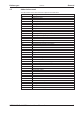
Setup 8.7 02/2015 Kollmorgen Warning messages Faults which occur, but which do not cause a switch-off of the amplifier output stage (BTB/RTO contact remains closed), are indicated in the LED display on the front panel by a coded warning number. Number E/S/A/P ... n01 n02 n03* n04* n05 n06* n07* n08 n09 n10* n11* n12 n13* n14 n15 n16 n17 n18 n19 n20 n21 n22 n23...
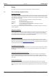
Kollmorgen 8.8 Setup 02/2015 Removing faults / warnings Depending on the conditions in your installation, there may be a wide variety of reasons for the fault. In multi-axis systems there may be further hidden causes of a fault. Detailled hints for removal of faults can be found in the Online Help, chapter "Trouble-Shooting". Our customer service can give you further assistance with problems.
Expansion Cards 9 Kollmorgen 02/2015 Expansion Cards Information about availability and order numbers can be found on p. 111 9.1 Guide to installation of expansion cards l Use a suitable screwdriver to unscrew the cover of the option slot. l 94 l Push the expansion card carefully into the provided guide rails of the main slot, without twisting it. l Press the expansion card firmly into the slot, until the front cover touches the fixing lugs. This ensures that the connectors make good contact.
Kollmorgen 9.2 Expansion Cards 02/2015 Expansion card -I/O-14/08This chapter describes the I/O-expansion card -I/O-14/08-. It only describes the additional features that the expansion card makes available for the SERVOSTAR 640/670. If you ordered the expansion card together with the servo amplifier, then it will be delivered already inserted into the expansion slot of the servo amplifier and screwed fast. The -I/O-14/08- provides you with 14 additional digital inputs and 8 digital outputs.
Expansion Cards 9.2.5 02/2015 Kollmorgen Connector assignments Connector X11A Terminal Dir 1 In 2 In 3 In 4 In 5 In 6 In 7 In 8 In 9 In 10 In 11 In 12 In Function A0 A1 A2 A3 A4 A5 A6 A7 Description Motion task no., LSB Motion task no., 21 Motion task no., 22 Motion task no., 23 Motion task no., 24 Motion task no., 25 Motion task no., 26 Motion task no., MSB Polls the reference switch.
Kollmorgen 9.2.
Expansion Cards 9.3 02/2015 Kollmorgen Expansion cards -PROFIBUSThis chapter describes the PROFIBUS expansion card for the SERVOSTAR 640/670. Information on the range of functions and the software protocol can be found in the manual "Communication profile PROFIBUS DP". The PROFIBUS expansion card has two 9-pin Sub-D sockets wired in parallel. The supply voltage for the expansion card is provided by the servo amplifier. 9.3.1 Front view 9.3.
Kollmorgen 9.4 02/2015 Expansion Cards Expansion card -SERCOSThis chapter describes the SERCOS expansion card for SERVOSTAR 640/670. Information on the range of functions and the software protocol can be found in the manual "IDN Reference Guide SERCOS". 9.4.1 Front view 9.4.2 Light emitting diodes (LEDs) RT TT ERR 9.4.3 indicates whether SERCOS telegrams are being correctly received. In the final Communication Phase 4 this LED should flicker, since cyclical telegrams are being received.
Expansion Cards 9.4.4 02/2015 Kollmorgen Connection diagram Layout of the SERCOS bus system in ring topology, with optical fibre cables (schematic). AGND and DGND (connector X3) must be joined together ! 9.4.5 Modifying the station address The drive address can be set to a value between 0 and 63. With address 0, the drive is assigned as an amplifier in the SERCOS ring.
Kollmorgen 9.5 02/2015 Expansion Cards Expansion card -DEVICENETThis section describes the DeviceNet expansion card for SERVOSTAR 640/670. Information on the range of functions and the software protocol can be found in our manual “DeviceNet Communication Profile”. 9.5.1 Front view 9.5.2 Connection technology Cable selection, cable routing, shielding, bus connector, bus termination and transmission times are all described in the “DeviceNet Specification, Volume I, II”, published by ODVA. 9.5.
Expansion Cards 9.5.4 02/2015 Kollmorgen Combined module/network status-LED LED Meaning The device is not online. - The device has not yet finished the Dup_MAC_ID test. off - The device is possibly not yet switched on. The device is operating as normal, is online, and the connections have been establisgreen hed. The device has been assigned to a master. The device is operating as normal, is online, but the connections have not been established.
Kollmorgen 9.5.7 02/2015 Expansion Cards Bus cable To meet ISO 898, a bus cable with a characteristic impedance of 120 W should be used. The maximum usable cable length for reliable communication decreases with increasing transmission speed. As a guide, you can use the following values which we have measured, but they are not to be taken as assured limits.
Expansion Cards 9.6 02/2015 Kollmorgen Expansion card -ETHERCATThis section describes the EtherCAT expansion card for SERVOSTAR 640/670. Information on the range of functions and the software protocol can be found in the EtherCAT documentation. This expansion cards enables the servo amplifier to be connected to the EtherCAT network via RJ-45 connectors (IN and OUT ports). 9.6.1 Front view 9.6.2 LEDs LED ERROR RUN ACT IN ACT OUT 9.6.
Kollmorgen 9.7 Expansion Cards 02/2015 Expansion card -SYNQNETThis section describes the SynqNet expansion card for SERVOSTAR 640/670. Information on the range of functions and the software protocol can be found in the SynqNet documentation.. 9.7.1 Front view 9.7.2 NODE ID Switch LED2 LED1 LED4 LED3 With these hexadecimal switches you can set the main and low significant bytes of the Node ID seperately.
Expansion Cards 9.7.5 02/2015 Kollmorgen Digital inputs/outputs, connector X21A (SubD 15-pin, socket) Inputs (In): 24V (20...
Kollmorgen 9.8 02/2015 Expansion Cards Expansion module -2CANConnector X6 of the SERVOSTAR is assigned to the signals for the RS232 interface and the CAN interface. It is therefore not the standard pin assignment for these interfaces, and a special cable is required to be able to use both interfaces simultaneously. The -2CAN- expansion module provides the interfaces on separate Sub-D connectors. The two CAN connectors are wired in parallel.
Expansion Cards 9.8.4 Connector assignments RS232 X6A Pin 1 2 3 4 5 6 7 8 9 9.8.
Kollmorgen 02/2015 Appendix 10 Appendix 10.
Appendix P R S T Z 110 02/2015 Kollmorgen P-controller Control loop with purely proportional behavior Phase shift Compensation for the lag between the electromagnetic and magnetic fields in the motor PID-controller Control loop with proportional, integral and differential behavior PID-T2 Filter time constant for the speed controller output Position controller Regulates the difference between the position setpoint and the actual position to 0 Output : speed setpoint Potential isolation Ele
Kollmorgen 10.2 Appendix 02/2015 Order codes The order numbers of accessories such as cables, brake resistors, mains supplies, etc., can be found in the accessories manual. 10.2.
Appendix 10.
Kollmorgen 10.4 02/2015 Index ! 24Vaux. supply, interface . . . . . . . . . . . 44 A A quad B interface . . . . . . . . . . . . . . . 59 Abbreviations . . . . . . . . . . . . . . . . . . 9 Address . . . . . . . . . . . . . . . . . . . . 87 Ambient conditions . . . . . . . . . . . . . . . 22 Ambient temperature. . . . . . . . . . . . . . 22 Analog outputs . . . . . . . . . . . . . . . . . 62 Assembly. . . . . . . . . . . . . . . . . . . . 33 BISS interface . . . . . . . . . . . . . . . . . 48 BTB/RTO.
Service We are committed to quality customer service. In order to serve in the most effective way, please contact your local sales representative for assistance. If you are unaware of your local sales representative, please contact the Customer Support. Europe KOLLMORGEN Customer Support Europe Internet www.kollmorgen.com E-Mail technik@kollmorgen.com Tel.: +49 (0)2102 - 9394 - 0 Fax: +49 (0)2102 - 9394 - 3155 KOLLMORGEN UK Website North America KOLLMORGEN Customer Support North America Internet www.