Model UT60B/C/E: OPERATING MANUAL Table of Contents Title Page Overview Unpacking Inspection Safety Information Rules For Safe Operation International Electrical Symbols The Meter Structure Rotary Switch Functional Buttons Display Symbols Measurement Ranges A. Selecting a Measurement Range B. Manual Ranging and Autoranging Measurement Operation A. DC Voltage Measurement B. AC Voltage Measurement C. Measuring Resistance D. Testing for Continuity E. Testing Diodes F. Capacitance Measurement G.
Model UT60B/C/E: OPERATING MANUAL Page E. Diode Test F. Capacitance G. Frequency & Duty Cycle H. Temperature (Model UT60C/UT60E) I. DC Current J. AC Current Maintenance A. General Service B. Testing the Fuses C. Replacing the Battery D. Replacing the Fuses RS232C Serial Port (Model UT60E) A. RS232C Port Cable B. Setting of RS232C Serial Ports C.
Model UT60B/C/E: OPERATING MANUAL Overview This Operating Manual covers information on safety and cautions. Please read the relevant information carefully and observe all the Warnings and Notes strictly. Warning To avoid electric shock or personal injury, read the “Safety Information” and “Rules for Safe Operation” carefully before using the Meter. Digital MultimeterModelUT60B, UT60Cand UT60E (hereafter referred to as “the Meter”) has autorange and manual range options with maximum reading 3999.
Model UT60B/C/E: OPERATING MANUAL Unpacking Inspection Open the package case and take out the Meter.
Model UT60B/C/E: OPERATING MANUAL Rules For Safe Operation Warning To avoid possible electric shock or personal injury, and to avoid possible damage to the Meter or to the equipment under test, adhere to the following rules: l Before using the Meter inspect the case. Do not use the Meter if it is damaged or the case (or part of the case) is removed. Look for cracks or missing plastic. Pay attention to the insulation around the connectors. l Inspect the test leads for damaged insulation or exposed metal.
Model UT60B/C/E: OPERATING MANUAL l l l l l l l cable and test clip from the Meter and turn the Meter power off before opening the Meter case. When servicing the Meter, use only the same model number or identical electrical specifications replacement parts. The internal circuit of the Meter shall not be altered at will to avoid damage of the Meter and any accident. Soft cloth and mild detergent should be used to clean the surface of the Meter when servicing.
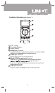
Model UT60B/C/E: OPERATING MANUAL The Meter Structure(see figure 1) (figure 1) 1 2 3 4 LCD Display Functional Buttons Rotary Switch HzV Input Terminal: Input for voltage, frequency/duty cycle, resistance, diode, continuity and capacitance measurements. 5 COM Input Terminal: Return terminal for all measurements. Model UT60B: Input Terminal: Input for 0.1 A to 400.0mA current measurements. Input Terminal: Input for 0.1 A to 400.0mA current measurements and temperature testing.
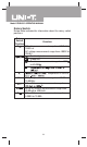
Model UT60B/C/E: OPERATING MANUAL Rotary Switch Below table indicated for information about the rotary switch positions. Rotary Switch Function Position V DC voltage measurement range from 400.0mV to 1000V or AC voltage measurement range from 4.000V to 750.0V. Continuity test. Diode test. Resistance measurement range from 400.0 to 40.00M . Temperature in celsius Hz mA A Frequency measurement range from 10.00Hz to 10.00MHz. AC or DC current measurement range from A.
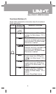
Model UT60B/C/E: OPERATING MANUAL Functional Buttons (1) Below table indicated for information about the functional button operations. Button Measuring Operation Performed Function POWER Any rotary Turn the power on and off. switch position Switches between AC and DC V voltage; the Meter beeps. DC is default. Model UT60B:Switches between continuity and diode and resistance measurements; the Meter beeps. Resistance is default.
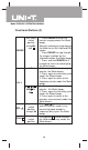
Model UT60B/C/E: OPERATING MANUAL Functional Buttons (2) l Press RANGE to enter the manual ranging mode; the Meter beeps. Manually selecting a range causes the Meter to exit the Hold and REL modes. RANGE l Press RANGE to step through the ranges available for the selected function; the Meter beeps. l Press and hold RANGE for 2 seconds to return to autoranging; the Meter beeps. 1. Press to start the frequency Hz counter; the Meter beeps. 2. Press again to enter duty cycle mode; the Meter beeps. 3.
Model UT60B/C/E: OPERATING MANUAL Display Symbols (1) (see figure 2) 2 3 4 5 6 7 8 9 10 11 12 ~ 16 17 1 18 (figure 2) Number Symbol Meaning 1 AC Indicator for AC voltage or current. Model UT60B/UT60C:The displayed value is the mean value. Model UT60E: The displayed value is the true rms value. 2 TRMS The Model UT60E: Indicator for true rms value. The Meter is in the auto range mode in 3 which the Meter automatically selects the range with the best resolution. 4 RS232C Data output.
Model UT60B/C/E: OPERATING MANUAL Display Symbols (1) (see figure 2) ,k , : M k : M : F: nF nF: Ohm. The unit of resistance. kilohm. 1 x 10 or 1000 ohms. Megaohm. 1 x 10 or 1,000,000 ohms. Farad. The unit of capacitance. Microfarad. 1 x 10 or 0.000001 farads. Nanofarad. 1 x 10 or 0.000000001 farads. Hz, Hz: Hertz. The unit of frequency in 12~16 kHz, cycles/second. MHz kHz: Kilohertz. 1 x 10 or 1,000 hertz. MHz: Megahertz. 1 x 10 or1,000,000 hertz. V, mV V: Volts. The unit of voltage. mV Millivolt.
Model UT60B/C/E: OPERATING MANUAL Measurement Ranges (2) l In the autorange mode, the Meter selects the best range for input signals. This allows you to switch test points without having to reset the range. l In the manual range mode, you may select the range. This allows you to override autorange and lock the Meter in a specific range. The Meter defaults to the autorange mode in measurement functions that have more than one range. When the Meter is in the autorange mode, is displayed.
Model UT60B/C/E: OPERATING MANUAL Measurement Operation (1) A.DC Voltage Measurement (see figure 3) (figure 3) Warning To avoid harms to you or damages to the Meter from electric shock, please do not attempt to measure voltages higher than 1000VDC / 750VAC rms although readings may be obtained. The DC Voltage ranges are: 400.0mV, 4.000V, 40.00V, 400.0V and 1000V. To measure DC voltage, connect the Meter as follows: 1.
Model UT60B/C/E: OPERATING MANUAL Measurement Operation (2) B. AC Voltage Measurement (see figure 4) (figure 4) Warning To avoid harms to you or damages to the Meter from electric shock, please do not attempt to measure voltages higher than 1000VDC / 750VAC rms although readings may be obtained. The AC voltage ranges are: 4.000V, 40.00V, 400.0V and 750.0V. To measure AC Voltage, connect the Meter as follows: 1. Insert the red test lead into the HzV terminal and the black test lead into the COM terminal.
Model UT60B/C/E: OPERATING MANUAL Measurement Operation (3) C.Measuring Resistance (see figure 5) (figure 5) Warning To avoid damages to the Meter or to the devices under test, disconnect circuit power and discharge all the high-voltage capacitors before measuring resistance. The resistance ranges are: 400.0 , 4.000k , 40.00k , 400.0k , 4.000M and 40.00M . To measure resistance, connect the Meter as follows: 1. Insert the red test lead into theHzV terminal and the black test lead into theCOM terminal. 2.
Model UT60B/C/E: OPERATING MANUAL Measurement Operation (4) l If reading with shorted test leads is not 0.5 , check for loose test leads, incorrect function selection, or enabled Data Hold function. l For high-resistance measurement ( ), it is normal to take several seconds to obtain a stable reading. l The LCD displays indicating open-circuit for the tested resistor or the resistor value is higher than the maximum range of the Meter.
Model UT60B/C/E: OPERATING MANUAL Measurement Operation (5) l When continuity testing has been completed, disconnect the connection between the testing leads and the circuit under test, and remove the testing leads away from the input terminals of the Meter. E. Testing Diodes (see figure 7) (figure 7) Warning To avoid possible damage to the Meter and to the device under test, disconnect circuit power and discharge all highvoltage capacitors before testing diodes.
Model UT60B/C/E: OPERATING MANUAL Measurement Operation (6) voltage drop reading of 0.5V to 0.8V; however, the reverse voltage drop reading can vary depending on the resistance of other pathways between the probe tips. l Connect the test leads to the proper terminals as said above to avoid error display. The LCD will display indicating diode being tested is open or polarity is reversed.The unit of diode is Volt (V), displaying the forward voltage drop readings.
Model UT60B/C/E: OPERATING MANUAL Measurement Operation (7) anode & black clip to cathode instead of using test leads as mentioned above. l To minimize the effect of capacitance stored in the test leads, the test lead should be as short as possible. To measure a small value of capacitance, use REL mode to remove the leads capacitance. Remaining voltage, insulated impedance, & dielectric absorption from the capacitor may cause the measurement error.
Model UT60B/C/E: OPERATING MANUAL Measurement Operation (8) l To obtain a stable reading when measuring input scope 30V rms frequency signal: Set the rotary switch to V . Then press Hz% to select Hz measurement mode to obtain frequency value. When input scope 30V rms, please follow the above step 2. carrying out the measurement. l When making frequency measurement at voltage or current range, please mind the following signal requirement table: Range Signal Requirement Frequency Range 4V 1.
Model UT60B/C/E: OPERATING MANUAL Measurement Operation (9) I. Model UT60C/UT60E: Temperature Measurement (see figure 10) (figure 10) The temperature measurement range is To measure temperature, connect the Meter as follows: 1. Insert the red temperature probe into the and the black temperature probe into the COM terminal. 2. Set the rotary switch to 3. Place the temperature probe to the object being measured. The measured value shows on the display.
Model UT60B/C/E: OPERATING MANUAL Measurement Operation (10) The current measurement has 3 measurement positions on the rotary switch: A , mA and A . The A has a 400.0 A and 4000 A range, with auto ranging; the mA has a 40.00mA and 400.0mA range, with auto ranging; A position has a 4.000A and 10.00A range, with auto ranging. To measure current, do the following: 1. Turn off power to the circuit. Discharge all high-voltage capacitors. 2.
Model UT60B/C/E: OPERATING MANUAL Operation of Hold Mode Warning To avoid possibility of electric shock, do not use Hold mode to determine if circuits are without power. The Hold mode will not capture unstable or noisy readings. The Hold mode is applicable to all measurement functions. l PressHOLD H to enter Hold mode; the Meter beeps. l PressHOLD H again orRANGE or Hz % or turn the rotary switch to exit Hold mode; the Meter beeps. l In Hold mode, is displayed.
The POWER button This is a self-lock switch use to turn on or off the power of the Meter. The BLUE button It uses for selecting the required measurement function when there is more than one function at one position of the rotary switch. Turning on the Display Backlight Warning In order to avoid the hazard arising from mistaken readings in insufficient light or poor vision, please use Display Backlight function. l Press and hold HOLD H for over 2 seconds to turn the Display Backlight on.
Model UT60B/C/E: OPERATING MANUAL General Specifications l Maximum Voltage between any Terminals and Grounding: 1000V. l Fused Protection for Input Terminal: Model UT60B:Glass fuse, 0.5A, 250V, fast type, 5x20mm. l Fused Protection for Input Terminal: Model UT60C/E: Glass fuse, 0.5A, 250V, fast type, 5x20mm. l Fused Protection for 10AInput Terminal: UT60B/C/E: Glass fuse, 10A, 250V, fast type, 5x20mm. l Maximum Display: Digital: 3999 l Measurement Speed: Updates 3 times/second.
Accuracy Specifications (1) Accuracy: (a% reading + b digits), guarantee for 1 year. o o Operating temperature: 23 C 5 C. Relative humidity: 75%. o Temperature coefficient: 0.1 x (specified accuracy)/1 C A. DC Voltage Overload Range Resolution Accuracy Protection 0.1mV 400mV (0.8%+3) 4V 1mV 1000V DC 750V AC rms 40V 10mV (0.8%+1) continuous. 100mV 400V 1V 1000V (1%+3) Remarks:Input impedance B.
Model UT60B/C/E: OPERATING MANUAL Accuracy Specifications (2) D Continuity Test Range Resolution Accuracy 400.0 0.1 Approximate 100 Remarks: l Buzzer beeps continuously. l Open circuit voltage approximate 0.45V. Overload Protection 1000Vp E. Diode Test Range Resolution Overload Protection Diode 1mV 1000Vp Remarks: l Open circuit voltage approximate 1.48V. l Displays approximate forward voltage drop reading 0.5V~0.8V. F.
Model UT60B/C/E: OPERATING MANUAL Accuracy Specifications (3) H.Temperature (Model UT60C/UT60E) Overload Protection: Glass fuse 0.5A, 250V, fast type, 5x20mm. I. DC Current 400 A 0.1 A 0.5A, 250V, fast type Glass fuse, 5x20 mm. 10A, 250V, fast type Glass fuse, 5x20 mm. Remarks: l 4A & 10A Range: For continuous measurement 10 seconds and interval not less than 15 minutes.
Model UT60B/C/E: OPERATING MANUAL Accuracy Specifications (4) J. AC Current 400 A 0.1 A 0.5A, 250V, fast type Glass fuse, 5x20 mm. 10A, 250V, fast type Glass fuse, 5x20 mm. Remarks: Model UT60B/UT60C: displays effective value of sine wave (mean value response). Model UT60E: displays true rms value. l 4A & 10A Range: For continuous measurement 10 seconds and interval not less than 15 minutes.
MAINTENANCE This section provides basic maintenance information including battery and fuse replacement instruction. Warning Do not attempt to repair or service your Meter unless you are qualified to do so and have the relevant calibration, performance test, and service information. To avoid electrical shock or damage to the Meter, do not get water inside the case. A. General Service l Periodically wipe the case with a damp cloth and mild detergent. Do not use abrasives or solvents.
l If the Meter beeps, the fuse is good. l If the display shows , replace the fuse and test again. l If the display shows any other value, have the Meter serviced and contact your dealer immediately. If the Meter does not work while the fuse is all right, send it to your dealer for repair. C. Replacing the Battery (see figure 12) (figure 12) Warning To avoid false readings, which could lead to possible electric shock or personal injury, replace the battery as soon as the battery indicator “ ” appears.
Model UT60B/C/E: OPERATING MANUAL D. Replacing the Fuses(see figure 13) (figure 13) Warning To avoid electrical shock or arc blast, or personal injury or damage to the Meter, use specified fuses ONLY in accordance with the following procedure. To replace the Meter’s fuse: 1. Press the POWER to turn the Meter off and remove all connections from the terminals. 2. Remove the screw from the battery compartment, and separate the battery compartment from the case bottom. 3.
Model UT60B/C/E: OPERATING MANUAL 6. Rejoin the battery compartment and the case top, and reinstall the screw. 7. Rejoin the case bottom and case top, and reinstall the 2 screws and 2 rubber feet. Replacement of the fuses is seldom required. Burning of a fuse always results from improper operation.
Model UT60B/C/E: OPERATING MANUAL RS232C Serial Port (Model UT60E) A.RS232C Port Cable The Meter Computer D-sub D-sub D-sub Pin Name 9 Pin Female 25 Pin Female B.Setting of RS232C Serial Ports Default of RS232C serial port for communication is set as: Baud Rate 2400 Start bit 1 (always 0) Stop bit 1 (always 1) Data bits 7 Parity Odd C.
Model UT60B/C/E: OPERATING MANUAL 36
Model UT60B/C/E: OPERATING MANUAL 37
Model UT60B/C/E: OPERATING MANUAL Copyright 2001 Uni-Trend International Limited. All rights reserved. Manufacturer: UNI-TREND TECHNOLOGY(DONG GUAN)LIMITED Address: Dong Fang Da Dao, Bei Shan Dong Fang Industrial Development District, Hu Men Town, Dong Guan City, Guang Dong Province, China Headquarters: Uni-Trend International Limited Address: Rm901, 9/F, Nanyang Plaza 57 Hung To Road Kwun Tong Kowloon, Hong Kong Tel: (852) 2950 9168 Fax: (852) 2950 9303 Email: info@uni-trend.com http://www.uni-trend.