
Specifications

info@tursdaletechnicalservices.co.uk
10
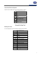
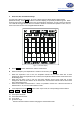
z Press Time button under scope mode, the corresponding functional button:
Base ▲ Base ▼ Base < Base >
F1 F2 F3 F4
F1: increase the number of periods
F2: decrease the number of periods.
F3: Trigger point move left
F4: Trigger point right move
The auto set feature will be off when changing the measurement mode.
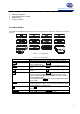
iii. Trigger function
Press Trig button under scope mode, the corresponding function buttons:
Trig ▲ Trig ▼ Auto/Norm/Shot Slop Rrise/Fall
F1 F2 F3 F4
F1: move the trigger level up
F2: move the trigger level down
F3: select the trigger mode: auto, normal or single
F4: slope adjustment: rise or fall
iv. Waveform data save and recall
Press Save/Call button under scope mode, the corresponding functional buttons:
Save/Call ▲ 1 ▼ Enter
F1 F2 F3 F4
F1: save or recall
F2 and F3: select location (location from 0-9, total 10 location)
F4: confirm
z When saving the data, it will overwrite the current data in the location no matter that location has
data or not.
z If you recall the location has no data, the meter will appear error message, you need to press HOLD
button to continue measurement,
z If you recall the location has data, it will save the current setting and display the data, the LCD top
left shows REV to indicate recalling mode is on. Press HOLD button to return to working mode and
continue measurement. You could continue recalling under recall mode or save the data.
z Recall mode can be used under any scope mode. For example, it is possible to recall the waveform
or data saved from voltage or frequency mode when the meter is under current measurement mode.
z Recall mode can be worked under any waveform mode. For example: the Meter is at current mode
but recalling the waveform or data which are saved under voltage or frequency mode. The Meter must be
returned to working mode to carry out measurement.
Remarks:
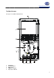
In order to have more accurate waveform, user can buy an optional BNC probe and scope probe to
decrease signal attenuates. The scope probe directly connect to the BNC probe.
When measuring voltage and frequency signal, connect the BNC black probe to the COM input terminal
and the red probe to the voltage terminal.
When measuring current signal, connect BNC black probe to the COM terminal and the red probe to mA
terminal.
Don’t connect the BNC probe to the 10A terminal.