
Specifications


info@tursdaletechnicalservices.co.uk
15
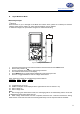
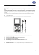
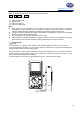
When measuring resistance, the corresponding functional buttons:
RES REL Rang ▲ Rang ▼
F1 F2 F3 F4
F1: toggle to diode mode
F2: relative mode
F3: select to a range up
F4: select to a range down
Note:
z When measuring low resistance, the test leads can add 0.1Ω to 0.2Ωof error to resistance
measurement. To test the leads, touch the probe tips together and read the resistance of the leads.
Take the reading obtained to subtract the resistance of the leads to get the final reading.
z For high-resistance measurement (>1MΩ) or low resistance measurement (<40Ω), it is normal taking
several seconds to obtain a stable reading.
z The LCD displays “OL” indicating open-circuit without input.
z When resistance measurement has been completed, disconnect the connection between the testing
leads and the circuit under test and remove testing leads away from the input terminals.
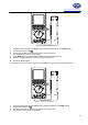
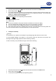
iv. Testing Diodes
Warning
To avoid harms to you, please do not attempt to input voltages higher than 60V DC or 42V rms AC.
To avoid damages to the Meter or to the devices under test, disconnect circuit power and discharge all
the high-voltage capacitors before testing diodes.
Use the diode test to check diodes, transistors, and other semiconductor devices. The diode test sends a
current through the semicondutor junction, then measure the voltage drop across the junction. A good
silicon junction drops between 0.5V and 0.8V
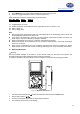
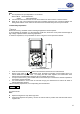
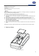
To test the diode out of a circuit, set up the Meter as Figure 3-7 and proceed as follows:
BlackRed
Figure 3-7. Diode Test