
Specifications


info@tursdaletechnicalservices.co.uk
16
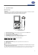
1. Insert the red test lead into the Ω terminal and the black test lead into the COM terminal.
2. Set the rotary switch to Ω
.
3. For forward voltage drop readings on any semiconductor component, place the red test lead on the
component’s anode and place the black test lead on the component’s cathode. The red test lead
polarity is “+” while the black test lead polarity is “— “.
The measured value shows on the display.
When measuring diode, the corresponding functional buttons:
DIODE REL
F1 F2
F1: toggle to continuity buzzer
F2: relative mode
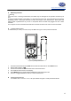
Note:
z Connect the test leads to the proper terminals as said above to avoid error display.
z The LCD will display OL indicating either open circuit or wrong polarity connection.
z The unit of diode is volt (V), displaying the positive-connection voltage-drop value.
z When diode testing has been completed, disconnect the connection between the testing leads and
the circuit under test and remove the test leads away from the input terminals.
v. Testing for Continuity
Warning
To avoid harms to you, please do not attempt to input voltage higher than 60V DC or 42V rms AC.
To avoid possible damages to the Meter or to the devices under test, disconnect circuit power and
discharge all the high-voltage capacitors before measuring continuity.
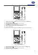
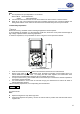
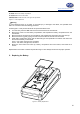
To test for continuity, set up the Meter as Figure 3-8 and do the following:
BlackRed
Figure 3-8. Continuity Test
1. Insert the red test lead into the Ω terminal and the black test lead into the COM terminal.
2. Set the rotary switch toΩ
.
3. Connect the test leads across with the object being tested.