
Specifications


info@tursdaletechnicalservices.co.uk
18
Note
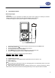
z The requirement of Input amplitude “a” is as follows:
When ≤1MHz: 300 mV≤a≤30Vrms;
>1MHz: 600 mV≤a≤5Vrms
z It is normal to have few seconds run time when switch from other functions to these functions.
z When Hz or duty cycle measurement has been completed, disconnect the connection between the
testing leads and the circuit under test and remove the test leads away from the input terminals.
vii. Measuring Capacitance
Warning
To ensure accuracy, the Meter inside is discharged against the tested capacitor
To avoid damage to the Meter or to the equipment under test, disconnect circuit power and discharge all
high-voltage capacitors before measuring capacitance.
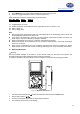
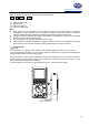
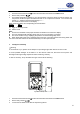
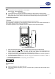
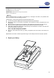
To measure capacitance, set up the Meter as shown in Figure 3-10 and proceed as follows:
BlackRed
Figure 3-10. Measuring Capacitance
1. Insert the red test lead into the
terminal and the black test lead into the COM terminal.
2. Set the rotary switch to
measurement mode, the Meter may display a fixed reading which is a
internal distributed capacitor value. For testing less than 40nF capacitor, the tested value must
subtract the internal distributed capacitor value to maintain the accuracy.
3. To improve the accuracy, press F2 REL with the test leads open to subtract the residual capacitance
of the Meter and the test leads.
4. It is recommended to use as short as test lead carrying out measurement to reduce the effect of
internal distributed capacitor.
When measuring capacitance, the corresponding functional buttons:
Capacity REL
F1 F2
F2: relative mode
Note:
z Capacitors larger than 10μF take longer time.
z If the tested capacitor has polarity, connect the red test lead to positive side and black test lead to
negative side.