
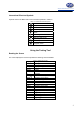
Specifications
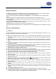

info@tursdaletechnicalservices.co.uk
5
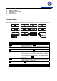
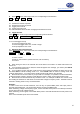
International Electrical Symbols
Symbols used on the Meter and in this manual are explained in Table1-2.
Table 1-2. International Electrical Symbols
AC or DC
DC Measurement
AC Measurement
Continuity Test
Diode
Grounding
Double Insulated
Warning. Re
f
er to the
O
p
eratin
g
Manual
Deficiency of Built-In Battery
C
on
f
orms to
S
tandards o
f
Euro
p
ean Union
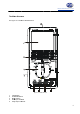
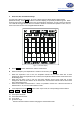
Using the Testing Tool
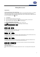
Reading the Screen
The screen displays the menu that provides the following choices available:
Table 2-1. Reading the Screen
Display Description
Contrast The degree of contrast
Auto Off Sleep mode time
BK Light Display backlight
BEEP Beeper on and off
ENTER Confirm
▲
Increase
▼ Decrease
MOVE ▲
Waveform moves up
MOVE ▼ Waveform moves down
RANG▲ Increase a range
RANG▼ Decrease a range
BASE ▲ Increase a time base
BASE ▼ Decrease a time base
BASE > Waveform moves right
BASE < Waveform moves left
TRIG▲ Trigger moves up
TRIG▼ Trigger moves down
SLOP Trigger slope adjustment
AUTO Auto trigger mode
NORM Normal trigger mode
SHOT Single trigger mode