Model UT90A: OPERATING MANUAL=VC220 Table of Contents Title Page Overview Unpacking Inspection Safety Information Rules For Safe Operation International Electrical Symbols The Meter Structure LCD Indicators Rotary Switch Functional Buttons Measurement Operation A. AC/DC Voltage Measurement B. AC/DC Current Measurement C. Resistance Measurement D. Diodes Measurement E. Continuity Measurement F. Power Voltage Measurement General Specifications Accuracy Specifications A. DC Voltage B. AC Voltage C.
Model UT90A: OPERATING MANUAL Overview This Operating Manual covers information on safety and cautions. Please read the relevant information carefully and observe all the Warnings and Notes strictly. Warning To avoid electric shock or personal injury, read the “Safety Information” and “Rules for Safety Operation” carefully before using the Meter.
Model UT90A: OPERATING MANUAL 3 certificate 1 piece In the event you find any missing or damage, please contact your dealer immediately. Safety Information This Meter complies with GB4793 standard for safety electrical measuring and test equipment, and IEC61010-1: in pollution degree 2, overvoltage category (CAT II 1000V, CAT III 600V) and double insulation. Use the Meter only as specified in this operating manual, otherwise the protection provided by the Meter may be impaired.
Model UT90A: OPERATING MANUAL to the following rules: l l l l l l l l l Before using the Meter inspect the case. Do not use the Meter if it is damaged or the case (or part of the case) is removed. Look for cracks or missing plastic. Pay attention to the insulation around the connectors. Inspect the test leads for damaged insulation or exposed metal. Check the test leads for continuity. Replace damaged test leads with identical model number or electrical specifications before using the Meter.
Model UT90A: OPERATING MANUAL l l l l l l readings. Remove test leads from the test circuit before changeover of range. Turn the Meter power off before connect the Meter to circuit and check the fuse before measuring current. When servicing the Meter, use only the same model number or identical electrical specifications replacement parts. The internal circuit of the Meter shall not be altered will to avoid damage of the Meter and any accident.
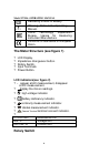
Model UT90A: OPERATING MANUAL Deficiency of Built-In Battery. Warning. Refer to the Operating Manual. China Technology Supervision Bureau, license for measuring instrument Manufacture Conforms to Standards of European Union. The Meter Structure (see figure 1) ? ? ? ? ? LCD Display. Impedance changeover button. Rotary Switch. Input Terminals. Power Button. LCD indicators(see figure 2) ? ~ appear at AC measurement, disappear at DC measurement. ? display the minus readings. ? high voltage indicator.
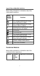
Model UT90A: OPERATING MANUAL Below table indicated for information about the rotary switch positions. Rotary Switch Positio n V V O A A Function DC voltage measurement range from 200.0mV to 1000V. AC voltage measurement range from 2.000V to 750.0V. OResistance measurement range from 200.0O to 20.00MO. Diode test. Continuity test. DC current measurement range from 200.0mA to 20.00A. AC current measurement range from 200.0µA to 20.00A. Power voltage measurement Turn on/off the Meter.
Model UT90A: OPERATING MANUAL Impeda nce change over button AC/DC voltage range It is used to inspect the resistance of supply power under 250V MAX.(? ? ? ? ? ? ) Any rotary switch position Turn the power of the Meter on or off. Measurement Operation A. AC/DC Voltage Measurement (see figure 3) Warning To avoid harms to you or damages to the Meter from electric shock, please do not attempt to measure voltages higher than 1000V DC/750V AC although readings may be obtained.
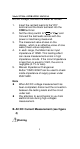
Model UT90A: OPERATING MANUAL AC/DC voltage, connect the Meter as follows: 1. 2. 3. 4. 5. Insert the red test lead into the“VO)” terminal and the black test lead into the COM terminal. Set the rotary switch to“V ”or“V ”,and Connect the test leads across with the power or load being measured. The measured value shows on the display, which is an effective value of sine wave (mean value response). In each range, the Meter has an input impedance of 10MO.
Model UT90A: OPERATING MANUAL To avoid damages to the built-in fuse and the Meter, please do not attempt parallel connect the test leads with any circuit while the test leads are inserted into the current terminal. For the safety requirement, when measure high current, every measure time should< 10 seconds and the time between two measurements should > 15 minutes. The measurement ranges of DC current are: 200mA,2mA,20mA,200mA,20A; The measurement ranges of AC current are: 200.0µA,2.000mA,20.00mA,200.
Model UT90A: OPERATING MANUAL completed, disconnect the connection between the test leads and measured circuit. C. Resistance Measurement(see figure 5) Warning To avoid injury to the user, please do not attempt the voltage higher than 60V/DC or 30V/AC. The resistance ranges are: 200.0O, 2.000kO, 20.00kO, 200.0kO, 2.000MOand 20.00MO. To measure resistance, connect the Meter as follows: 1. 2. 3. Insert the red test lead into the VO terminal and the black test lead into the COM terminal.
Model UT90A: OPERATING MANUAL precision readings in low-resistance measurement, that is the range of 200.0O, short-circuit the input terminals beforehand and record the reading obtained (called this reading as X). (X) is the additional resistance from the test lead. Then use the equation: measured resistance value (Y) - (X) = precision readings of resistance. l When the resistance reading=0.5Oin the shorten-circuit, please check for loose test leads or other reasons.
Model UT90A: OPERATING MANUAL To test a diode out of a circuit, connect the Meter as follows: 1. 2. 3. Insert the red test lead (anode “+”) into the terminal and the black test lead VO (cathode “-”) into the COM terminal. Set the rotary switch to , place the red test lead on the component’s anode and place the black test lead on the component’s cathode. For forward voltage drop readings on any semiconductor component, the measured value shows on the display and the unit of diodes measurement is mV.
Model UT90A: OPERATING MANUAL disconnect the connection between the testing leads and the circuit under test. E. Continuity Measurement(see figure 7) Warning To avoid injury to the user, please do not attempt the voltage higher than 60V/DC or 30V/AC. To avoid damages to the Meter or to the devices under test, disconnect circuit power and discharge all the capacitors before measuring continuity. To test for continuity, connect the Meter as below: 1.
Model UT90A: OPERATING MANUAL capacitors. l l Open-circuit voltage of continuity measurement is about 3V. When continuity testing has been completed, disconnect the connection between the testing leads and the circuit under test. F. Power Voltage measurement(see figure 8) Warning To avoid damage to the inside fuse and the Meter, please do not attempt using battery and power of any other specification to measure except prescribed as Note. The measure the power voltage, connect the Meter as follows: 1.
Model UT90A: OPERATING MANUAL l The range of 9V only fit for the measure of 9V Battery, inside load resistance is 38O. General Specifications l Maximum Voltage between any Input Terminals and COM Terminal: 1000Vp. l Fuse protection of µA mA terminal: 300mA 250V fast melt fuse. l Fuse protection of 20A terminal: 20mA 250V fast melt fuse. l Equipped with full icons display. l Maximum Display: Display: 1999. l Measurement Speed: Updates 2-3 times /second. l Range: Manual. l Polarity: Automatically display.
Model UT90A: OPERATING MANUAL Accuracy: ±(a% reading + b digits), guarantee for 1 year. Operating temperature: 18 - 28? . Relative humidity: =75%RH. A.DC Voltage Range Resolution Accuracy: ±(a% reading + b digits) 200mV 0.1mV 2V 1mV ±(0.5%+2) 20V 10mV 200V 100mV 1000V 1V ±(0.8%+3) Remark: ?Input impedance: 10MO. ?Overload Protection: 1000V DC or 750V AC continuously measure(except 200mV 230V AC). B.AC Voltage Range Accuracy: ±(a% reading + b digits) Resolution 2V 1mV ±(0.
Model UT90A: OPERATING MANUAL C.DC Current Range Resolution Accuracy: ±(a% reading + b digits) 200mA 0.1µA 2mA 1µA ±(0.8%+2) 20mA 10µA 200mA 0.1mA 20A 10mA ±(1.2%+5) Remarks: ?Overload Protection: AtµA mA range: Fuse 5×20mm F0.3A 250V. At A range: Fuse 6×25mm F20A 250V. continuous measure time< 10 seconds. time between two measurements> 15 minutes. D. AC Current Range Resolution Accuracy: ±(a% reading + b digits) 200µA 0.1µA 2mA 1µA ±(1.0%+5) 20mA 10µA 200mA 0.1mA 20A 10mA ±(2.
Model UT90A: OPERATING MANUAL time between two measurements> 15 minutes. E. Resistance Range Resolution Accuracy: ±(a% reading + b digits) 200O 0.1O 2kO 1O 20kO 10O ±(0.8%+3) 200kO 100O 2MO 1kO 20MO 10kO ±(1.2%+5) Remarks: ?Overload Protection: 230V rms. F. Diodes Test Range Resolution 1mV Remark Open-circuit voltage is about 3V; transistor PN normal voltage is about 0.5~0.8V. Remarks: ?Overload Protection: 230V rms. G.
Model UT90A: OPERATING MANUAL 1O Open circuit voltage is about 3V; Set the resistance of a open circuit> 100O, buzzer will not sound; Set the resistance of a well connected circuit=10O, buzzer sounds continuously. Remark: ?Overload Protection: 230V rms. Fuse Replacement(see figure 9) Warning To avoid electrical shock or injury to the user because of wrong readings of the Meter, please inspect the damage of fuse inside when there is not any response on the display during current measurement.
Model UT90A: OPERATING MANUAL Warning Before remove the case bottom, make sure the power is off, remove the test leads from terminals and test circuit. l l l Periodically wipe the case with a damp cloth and a little mild detergent. Do not use chemical abrasives or solvents. Please stop any operation of the Meter and sent it outside to repair or service if there is anything wrong.