
Specifications

11
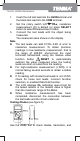
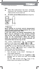
1. Insert the red test lead into the HzVȍterminal and
the black test lead into the COM terminal.
2. Set the rotary switch toȍ
, resistance
measurement (ȍ) is default (or press SELECT
button to selectȍmeasurement mode)
3. Connect the test leads with the object being
measured.
The measured value shows on the display.
Note
z The test leads can add 0.1ȍto 0.2ȍ of error to
resistance measurement. To obtain precision
readings in low-resistance measurement, that is
the range of 400.0ȍ, short-circuit the input
terminals beforehand, using the relative value
function button
RESET to automatically
subtract the value measured when the testing
leads are short-circuited from the reading.
z For high-resistance measurement (>1Mȍ), it is
normal taking several seconds to obtain a stable
reading.
z If ȍ reading with shorted test leads is not 0.5ȍ,
check for loose test leads, incorrect function
selection, or enabled Data Hold function.
z The LCD displays OL indicating open-circuit for
the tested resistor or the resistor value is higher
than the maximum range of the Meter.
z When resistance measurement has been
completed, disconnect the connection between
the test leads and the circuit under test.
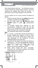
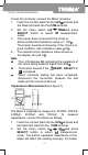
Testing Diodes (see figure 5)
Use the diode test to check diodes, transistors, and
72-9375: OPERATING MANUAL