
Specifications

12
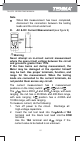
other semiconductor devices. The diode test sends a
current through the semiconductor junction, and then
measures the voltage drop across the junction. A
good silicon junction drops between 0.5V and 0.8V.
To test a diode out of a circuit, connect the Meter as
follows:
1. Insert the red test lead into the HzVȍterminal and
the black test lead into the COM terminal.
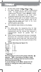
2. Set the rotary switch toȍ
and press
SELECT button to select
measurement
mode.
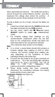
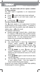
3. For forward voltage drop readings on any
semiconductor component, place the red test
lead on the component’s anode and place the
black test lead on the component’s cathode.
The measured value shows on the display.
Note
z In a circuit, a good diode should still produce a
forward voltage drop reading of 0.5V to 0.8V;
however, the reverse voltage drop reading can
vary depending on the resistance of other
pathways between the probe tips.
z Connect the test leads to the proper terminals as
listed above. The LCD will display OL indicating
open-circuit for wrong connection. The unit of
diode is Volt (V), displaying the
positive-connection voltage-drop value.
z When diode testing has been completed,
disconnect the connection between the testing
leads and the circuit under test.
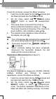
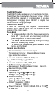
Continuity Testing (see figure 6)
72-9375: OPERATING MANUAL