
User Guide

19
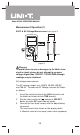
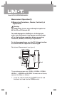
Measurement Operation(6)
red black
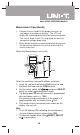
( figure 6)
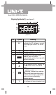
Model UT90C: OPERATING MANUAL
l Connect the test leads to the proper terminals as
said above to avoid error display. The LCD will
display OL indicating open-circuit for wrong connection.
The unit of diode is Volt (V), displaying the positive-
connection voltage-drop value.
l When diode testing has been completed, disconnect
the connection between the testing leads and the
circuit under test.
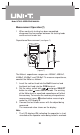
Continuity Measurement (see figure 6)
To test for continuity, connect the Meter as below:
1. Insert the red test lead into the HzVΩ terminal and
the black test lead into the COM terminal.
2. Set the rotary switch toΩ and press SELECT
button to select measurement mode.
3. The buzzer does not sound if the circuit is disconnected
with resistance value is > 100Ω
The buzzer sounds continuously if the circuit is in
good condition with resistance value 10Ω.
4. The nearest circuit resistance value shows on the
display, the unit isΩ.
Note
l The LCD displays OL indicating the resistance of
the circuit being tested is higher than 400Ω.
l The buzzer sounds once if the RESET, SELECT
or is pressed on.