UNI-T. Preface Thank you for purchasing the new function generator. In order to use this product safely and correctly, please read this manual thoroughly, especially the Safety Information part. After reading this manual, it is recommended to keep the manual at an easily accessible place, preferably close to the device, for future reference.
UNI-T. Copyright Information Uni-Trend Technology (China) Co., Ltd, all rights reserved. UNI-T products are protected by patent rights in China and other countries, including issued and pending patents. Uni-Trend reserves the rights to any product specification and pricing changes. Uni-Trend reserves all rights. Licensed software products are properties of Uni-Trend and its subsidiaries or suppliers, which are protected by national copyright laws and international treaty provisions.
Table of Contents Preface a Copyright Information me me Table of Contents ——- Chapter 1 Safety Information eee 1.1 Safety Terms and Symbols 1.2 General Safety Overview Chapter 2 Introduction a a 2.1 Main Feature Sa 2.2 Output Features 2.3 Panels and Buttons Introduction 2.3.1 Front Pane! =e 2.3.2 Left and Right Pane! -e2.3.3 Function Interface 3.1 General Inspection nnn 3.1.2 Check Accessories 3.1.3 Inspect the Device Basic Waveform Output 3.2.1 Set Output Frequency 3.2.2 Set Output Amplitude 3.2.
UNI-T. Chapter 1 Safety Information 1.1 Safety Terms and Symbols The following terms may appear in this manual: Warning: The conditions and behaviors may endanger life. Note: The conditions and behaviors may cause damage to the product and other properties. The following terms may appear on the product: Danger: This operation may cause immediate damage to the operator. Warming: This operation may cause potential damage to the operator.
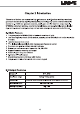
UNI-T. Chapter 2 Introduction This series of devices are economical, high-performance, multi-functional arbitrary waveform generators that use direct digital synthesis (DDS) technology to produce accurate and stable waveform. UTG900 can generate accurate, stable, pure and low distortion output signals. UTG900's convenient interface, superior technical indexes and user-friendly graphical display style can help users to complete study and test tasks quickly and improves work efficiency. 2.
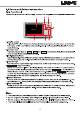
UNI-T. 2.3 Panels and Buttons Introduction 2.3.1 Front Panel The product provides users with a simple, intuitive, and easy-to-use front panel, as shown below: Display screen 4.3 inches TFT color LCD screen distinguishes the output status, function menu and other key information of CH1 and CH2 by various colors. User-friendly graphical display style improves work efficiency. 2.
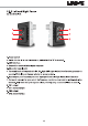
UNI-T. 2.3.2 Left and Right Panel As shown below: Power switch Switch it to the “I” to turn the device on, and switch turn it off. . USB interface Connect the device with the upper computer . DC power supply port The rated input of this product is 5V, 2A. High SNR signal output from function generator is needed. Official standard power adapter is recommended. .
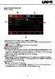
UNI-T. 2.3.3 Function Interface As shown below: ® 1. CH1 information, the selected channel will be highlighted. High Z indicates the matched impedance of output terminal (1Q to 999Q adjustable or high resistance; defaults to High Z) EEE : sine wave currently (Different modes have different menu) 2. CH2 information, as same as Ch1 3.
UNI-T. Chapter 3 Quick Start 3.1 General Inspection It is recommended to follow the steps below to check the instrument before using this device for the first time. 3.1.1 Check for Damages Caused by Transport If the packaging carton or foamed plastic cushions are severely damaged, please contact the UNI-T distributor of this product or local office.
UNI-T. 3.2.6 Set Ramp Symmetry The ramp wave default frequency is kHz. To set the triangular wave with symmetry of 75%, the specific steps are as follows: Press nd — [Symmetry], enter 75 by numeric keypad, and select the parameter uni 3.2.7 Set DC Voltage The default DC voltage is OV, and the specific steps to change it to 3V are as follows: Press — [DC], enter 3 by numeric keypad, and select the parameter unit |V|. 3.2.
UNI-T. 3.3.2 Frequency Counter This instrument can measure the duty ratio and frequency of TEL-compatible level signal, with frequency range of 100mHz-100MHz. When we use the frequency counter function, the TEL-compatible level signal inputs through an external digital modulation or frequency counter interface (INPUTTING connector) read the signal values of [Freq], and [Duty]. When there is no signal input, the counter parameter list will display the value measured before.
UNI-T. 3. Language Set the device language to English or simplified Chinese. 4. Beep Set the key pressing sound to "On" or "Off". 5. Num Format Set the separator between numbers, press | Formation | to select | Comma|, | Space | or [None |. 6. Back light Adjust the brightness of screen, press | Fightback to select between 30%, |50% |, 7. Screen Lock Press Screen Lock and select Off, 1 min, 5 min, 15 min, 30 min or 1h.
UNI-T. Chapter 4 Advanced Applications This chapter introduces the AM, PM, FM and FSK modulation. Press Mode to enter modulation, and press Mode again to exit. 4.1 Generate Modulation Waveform 4.1.1 Amplitude Modulation (AM) In AM modulation, modulated waveform is usually composed of carrier wave and modulation wave. The modulation of CH1 and CH2 are independent, you can set up the same or different mode for them.
UNI-T. ® Set Carrier Wave Frequency Default frequency is kHz. Different carrier waveform has different settable frequency range. Frequency Carer UTG93ZE Utahan Maximum Minimum Maximum Minimum Sine wave THz MHz 1uHz MHz Square wave zephyr MHz zephyr MHz Ramp wave 1uHz 400kHz 1uHz 400kHz Pulse wave 1uHz MHz 1uHz MHz Arbitrary wave zephyr MHz 1uHz MHz Use multi-functional knob to set carrier wave frequency after select carrier wave, or press then enter number by numeric keypad to set.
UNI-T. ® Set Modulation Wave Frequency Set the modulation wave frequency in range of 2mHz~200kHz (default to 100Hz). After enabling AM function, the default modulation wave frequency can be modified by multi-functional knob or press Mod Freq, enter the number by numeric keypad select unit. ® Set Modulation Depth Modulation depth indicates the extent of amplitude variation which is expressed as percentage.
UNI-T. 3) Set Waveform and Parameter of Carrier Wave Signal Press Press Wave — Square to select the square wave as carrier waveform (default to sine wave). Press to set the duty ratio, enter 45 by numeric keypad, and select the parameter unit As shown below: 4) Set Modulation Depth After setting carrier wave and parameters, press [Mode|— to enter the amplitude setting. Press [Depth], enter 80 and select the parameter unit [% | for setting modulation depth.
UNI-T. 5) Enable Channel Output Press to enable the channel 1 output quickly. Back light of the CH1 key will be tum on. The AM modulation waveform in oscilloscope is shown below: 4.1.2 Phase Modulation (PM) In phase modulation, modulated waveform is usually composed of carrier wave and modulation. The phase of carrier wave varies with amplitude of modulation wave. Press |to turn on the PM function, the device will output modulated waveform with current set modulation waveform and carrier wave.
UNI-T. ® Select Carrier Waveform PM carrier waveform can be: sine wave (default), pulse wave, ramp wave or arbitrary wave. After selecting the PM modulation, press to select carrier waveform. Set the Carrier Frequency Please refer to the AM carrier waveform setting. Select the Modulation Wave Modulation source of device is internal. And modulation wave can be: sine wave (default), square wave, rising/falling ramp wave, arbitrary wave or noise.
UNI-T. ® Set Modulation Wave Frequency Set the modulation wave frequency, range is 2mHz~200kHz (default to 100Hz). After enabling PM function, the default modulation wave frequency can be modified by multi-functional knob or press [Modifier, enter the number by numeric keypad and select unit. ® Set Phase Deviation The phase deviation indicates the change between the phases of PM modulated waveform and the phase of carrier wave phase.
UNI-T. 3) Set Waveform and Parameter of Carrier Wave Signal Press to select sine wave (default) as carrier waveform. Press Freq to set frequency, enter 800 by numeric keypad, and select parameter unit [Hz]. Press to set amplitude, enter 100, and select parameter unit [MVP. As the picture shown: 4) Set Phase Deviation After setting the carrier wave parameters, press to enable PM function.
UNI-T. 5) Enable Channel Output Press to enable the channel 1 output quickly. Back light of the CH1 key will be turn on. The PM modulation waveform in oscilloscope is shown below: 4.1.3 Frequency Modulation (FM) In FM modulation, modulated waveform is usually composed of carrier wave and modulation wave. The frequency of carrier wave will vary with amplitude of modulation wave. Press enable the FM function, the device will output modulated waveform with current set modulation waveform and carrier wave.