Unibrain Ultra Compact firewire cameras Models: 530/630/830 User Operation Manual Version 1.
Legal Notice For Customers in U.S.A. This equipment has been tested and found to comply with the limits for a Class B digital device, pursuant to Part 15 of the FCC Rules. These limits are designed to provide reasonable protection against harmful interference when the equipment is operated in a commercial environment.
Before You Start This manual should help you in installation and setting of the camera and we recommend you to carefully follow the instruction described. To ensure that your warranty remains valid, read the manual carefully before using the camera. DO NOT disassemble, modify or repair the camera since there is no user serviceable part inside and may void warranty. For prevention of fire or electric shock DO NOT remove screws or cover from the camera.
Table of contents 1. Introduction .................................................................................................................. 1 1.1. Overview ............................................................................................................................................................ 1 1.2. Dimensions and Description................................................................................................................................. 2 1.3.
3.8. Gain ................................................................................................................................................................. 24 3.9. Trigger & Strobe ............................................................................................................................................... 24 3.9.1. Supported Trigger .......................................................................................................................................
SIO (RS232) RX Control Procedure.............................................................................................................................. 47 SIO (RS232) TX Control Procedure Method I ............................................................................................................... 48 SIO (RS232) TX Control Procedure Method II .............................................................................................................. 49 4.9.2. SIO(RS232) Registers .......
Unibrain Fire-i 530/630/830 Operation Manual 1. 1.1. Page 1 Introduction Overview Unibrain’s new Fire-i ultra compact Industrial Firewire cameras Series opens up a new horizon in digital image processing; by providing more features in a very small form factor while still maintaining excellent cost effectiveness and high quality. These models are comprised of a wide range of resolutions and are equipped with a FireWire interface and a trigger to suit the needs of every application.
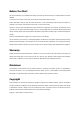
Unibrain Fire-i 530/630/830 Operation Manual 1.2. Page 2 Dimensions and Description Camera Body Size Camera Body Weight: : 29 (w) x 29 (H) x 39(D) mm approx. 63 gram Operation Temperature: -5°C ~ 45°C / Storage Temperature: -20°C ~ 65°C Avoid operation in environment of high humidity over 90% and allow sufficient airflow for prevention of heat buildup. 1.3.
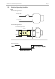
Unibrain Fire-i 530/630/830 Operation Manual 1.4. Page 3 Firewire Port The industry standard FireWire (IEEE-1394) port has the following pin assignment. Data and control of the camera and power are provided by the firewire port. Pin Signal 1 VP 2 VG(Ground) 3 TPB- 4 TPB+ 5 TPA 6 TPA- CAUTION: DO NOT reverse the polarity. This could result in damage to the camera. 1.4.1. Trigger Connector Port External Trigger Connector provides the access to multiple I/O.
Unibrain Fire-i 530/630/830 Operation Manual 1.5. Page 4 Electrical Operating Condition Trigger Recommended Trigger Example 1 Ext. Trigger signal Ext. trigger GND Recommended Trigger Example 2 Recommended Trigger Example Camera Side User Side External Trigger Pin Trigger Opto.
Unibrain Fire-i 530/630/830 Operation Manual Page 5 Strobe Recommended Strobe Example 1 Strobe signal Strobe GND Recommended Strobe Example 2 Recommended Strobe Example Strobe Camera Side User Side 220 Ω Strobe Pin Active High FT Series Camera GND GND Pin Opto.
Unibrain Fire-i 530/630/830 Operation Manual 1.6. Page 6 Pixel Data The Unibrain Fire-i ultra compact form Series complies with the IIDC 1394-Based Digital Camera Specification V1.31 where data packets are transmitted by a FireWireTM interface as isochronous packets. Every video format, mode and frame rate has a different video data format. (Pixel data source: IIDC V1.
Unibrain Fire-i 530/630/830 Operation Manual Page 7 U-(K+Pn-8) Y-(K+Pn-8) Y-(K+Pn-7) V-(K+Pn-8) Y-(K+Pn-6) Y-(K+Pn-5) U-(K+Pn-4) Y-(K+Pn-4) Y-(K+Pn-3) V-(K+Pn-4) Y-(K+Pn-2) Y-(K+Pn-1) Y-(K+0) Y-(K+1) Y-(K+2) Y-(K+3) Y-(K+4) Y-(K+5) Y-(K+6) Y-(K+7) Y-(K+Pn-8) Y-(K+Pn-7) Y-(K+Pn-6) Y-(K+Pn-5) Y-(K+Pn-4) V-(K+Pn-3) Y-(K+Pn-2) Y-(K+Pn-1) High Byte Low Byte Y-(K+0) Y-(K+1) Y-(K+2) Y-(K+3) Y-(K+Pn-4) Y-(K+Pn-3) V-(K+Pn-2) Y-(K+Pn-1) Data
Unibrain Fire-i 530/630/830 Operation Manual Page 8 Each component has 8 bit data. The data type is “Straight Binary” Highest(+) Lowest Lowest Signal Level (Decimal) Data (Hexadecimal) 127 0xFF 126 0xFE . . . . 1 0x81 0 0x80 -1 0x7F . . . . -127 0x01 -128 0x00 Y component has 16 bit data. The data type is “Unsigned Short (big-endian)” Y Signal Level (Decimal) Data (Hexadecimal) Highest 65535 0xFFFF 65534 0xFFFE . . . .
Unibrain Fire-i 530/630/830 Operation Manual 2. Page 9 Camera Specifications 2.1. Monochrome cameras 2.1.1. Fire-i 830b Specification Features Image Sensor Type 1/1.8-inch Interline CCD (Sony ICX274AL) Effective pixels 2,010,000 pixels 1628(H) x 1236(V) Picture Size 1600x1200, 1280x960, 1024x768, 800x600, 640x480 Cell Size(um) 4.4 x 4.4 15, 7.5, 3.75, 1.
Unibrain Fire-i 530/630/830 Operation Manual Page 10 2.1.2. Fire-i 630b Specification Features Image Sensor Type 1/3-inch Interline CCD (Sony ICX204AL) Effective pixels 800,000 pixels 1034(H) x 779(V) Picture Size 1024x768, 800x600, 640x480, 320x240 Cell Size(um) 4.65x4.65 30, 15, 7.5, 3.75, 1.
Unibrain Fire-i 530/630/830 Operation Manual Page 11 2.1.3. Fire-i 530b Specification Features Image Sensor 1/3-inch Interline CCD (Sony ICX424AL) Effective Pixels 330,000 pixels Picture Size 640 x 480, 320 x 240 Cell Size 7.40 x 7.40 659(H) x 494(V) 60, 30, 15, 7.5, 3.75, 1.
Unibrain Fire-i 530/630/830 Operation Manual 2.2. Page 12 Color Cameras 2.2.1. Fire-i 830c Specification Features Image Sensor Type 1/1.8-inch Interline CCD (Sony ICX-274AQ) Effective pixels 2,010,000 pixels 1600(H) x 1200(V) Picture Size 1600x1200, 1280x960, 1024x768, 800x600, 640x480 Cell Size(um) 4.4 x 4.4 15, 7.5, 3.75, 1.
Unibrain Fire-i 530/630/830 Operation Manual Page 13 2.2.2. Fire-i 630c Specification Features Image Sensor Type 1/3-inch Interline CCD (Sony ICX-204AK) Effective pixels 800,000 pixels 1034(H) x 779(V) Picture Size 1024x768, 800x600, 640x480, 320x240 Cell Size(um) 4.65 x 4.65 30, 15, 7.5, 3.75, 1.
Unibrain Fire-i 530/630/830 Operation Manual Page 14 2.2.3. Fire-i 530c Specification Features Image Sensor Type 1/3-inch Interline CCD (ICX-424AQ) Effective pixels 330,000 pixels Picture Size 640 x 480, 320 x 240 Cell Size(um) 7.40 x 7.40 659(H) x 494(V) 60, 30, 15, 7.5, 3.75, 1.
Unibrain Fire-i 530/630/830 Operation Manual 2.3. Page 15 Spectral Sensitivity Excludes lens and light source characteristics. 2.3.1.
Unibrain Fire-i 530/630/830 Operation Manual Spectral Sensitivity for Page 16 Fire-i 530b
Unibrain Fire-i 530/630/830 Operation Manual Page 17 2.3.2.
Unibrain Fire-i 530/630/830 Operation Manual Spectral Sensitivity for Page 18 Fire-i 530c
Unibrain Fire-i 530/630/830 Operation Manual 3. Page 19 Basic Operation and Features The Unibrain cameras employ a progressive scan CCD sensor which provides different features for each model. Basic functions and features are similar, while each camera has its own specific function support. The cameras- fully support the IIDC V1.31 specification with regards to registers, video format, mode of operation and control. 3.1.
Unibrain Fire-i 530/630/830 Operation Manual Page 20 1: Control with value in Absolute value CSR if this bit =1, value in Value filed is ignored One_Push [2..4] [5] Reserved Write ‘1’: begin to work(Self cleared after operation) Read : Value=’1’ in operation Value =’0’ not in operation If A_M_Mode=1, this bit is ignored On/OFF [6] Write : ON or OFF this feature Read : read a status 0: OFF, 1:ON If this bit=0, other fields will be read only.
Unibrain Fire-i 530/630/830 Operation Manual Page 21 0:OFF, 1:ON If this bit=0, other fields will be read only. A_M_Mode [7] Write: set the mode, Read: read a current mode 0: Manual, 1:Auto - [8..19] Reserved Value [20..31] Value : Write the value in Auto mode, this filed is ignored. If “ReadOut” capability is not available, read value Has no meaning 3.3. Sharpness The sharpness control feature may be used to compensate low-pass effects caused for instance by the special color interpolation.
Unibrain Fire-i 530/630/830 Operation Manual Page 22 Status Control Register Address Name Field Bit Description 80Ch WHITE_BAL Presence_Inq [0] Presence of this feature. 0:N/A 1:Available ANCE Abs_Control [1] Absolute value control 0: Control with value in the Value field 1: Control with value in the Absolute value CSR If this bit = 1, value in the Value field is ignored. - [2..
Unibrain Fire-i 530/630/830 Operation Manual Page 23 4000 4095 3500 3000 Gamma=2.5(25) 2500 Gamma=1.0.(10) 2000 1500 Gamma=0.4(4) 1000 500 4095 0 0 500 1000 1500 2000 2500 3000 3500 4000 Gamma Range Table Gamma Value Gamma Gamma Value Gamma 3.7. 4 5 6 7 8 9 10 11 12 13 14 0.4 0.5 0.6 0.7 0.8 0.9 1.0 1.1 1.2 1.3 1.4 15 16 17 18 19 20 21 22 23 24 25 1.5 1.6 1.7 1.8 1.9 2.0 2.1 2.2 2.3 2.4 2.
Unibrain Fire-i 530/630/830 Operation Manual Page 24 2903~3304 100ms T= (Y-2902)*100+5800 ms 5.9s ~ 46s 3305~3508 1s T= (Y-3304)*1000+46000 ms 47s ~ 250s 3509~3843 10s T= (Y-3508)*10 + 250 s 260s ~ 3600s Shutter Speed Example Example Shutter Speed Table 3.8.
Unibrain Fire-i 530/630/830 Operation Manual Page 25 3.9.1. Supported Trigger Edge Trigger Rising Edge or Falling Edge Mode 0, Source 1, 2, 3, 4, 5, 14, 15 External or Software Trigger Inquiry Register Address 530h Name Field Bit TRIGGER_I Presence_Inq [0] Presence of this feature Abs_Control_Inq [1] Capability of control with absolute value NQ - [2..
Unibrain Fire-i 530/630/830 Operation Manual 3.9.2.
Unibrain Fire-i 530/630/830 Operation Manual 3.9.3. Timing Diagram for External Trigger and Shutter and Strobe This diagram shows the necessary time related to each signal for External trigger and Shutter and Strobe.
Unibrain Fire-i 530/630/830 Operation Manual Page 28 3.9.4. Trigger Mode 0 The Camera starts integration of the incoming light from the external trigger input falling edge. The Integration time is described in the "Shutter" register. No parameter is needed. 3.9.5. Trigger Mode 1 The camera starts the integration of the incoming light from the external trigger input falling edge. The integration time is equal to the low state time of the external trigger input. No parameter is needed. 3.9.6.
Unibrain Fire-i 530/630/830 Operation Manual Page 29 3.9.7. Trigger Mode 3 Not supported at Format 7 Mode This is an internal trigger mode. The camera will issue a trigger internally and the cycle time is N times (parameter) the cycle time of the fastest frame rate. The Integration time of the incoming light is described in the “Shutter” register. A Parameter is required and shall be one or more (N>=1). 3.9.8. Trigger Mode 4 This mode is the “multiple shutter preset mode”.
Unibrain Fire-i 530/630/830 Operation Manual Page 30 3.9.9. Trigger Mode 5 This mode is the “multiple shutter pulse width mode”. The camera starts the integration of the incoming light from the first external trigger input falling edge and exposes the incoming light until the trigger is inactive. Repeat this sequence for the N-th (parameter) external trigger input falling edge and then finish integration. A parameter is required and shall be one or more. (N >= 1) 3.9.10.
Unibrain Fire-i 530/630/830 Operation Manual Page 31
Unibrain Fire-i 530/630/830 Operation Manual 3.10. Page 32 Strobe Control Register Base Address: 0xF2F23000h Address 000h Name Strobe_CTRL_Inq Field Bit Description Strobe_0_Inq [0] Presence of strobe 0 signal Strobe_1_Inq [1] Presence of strobe 1 signal Strobe_2_Inq [2] Presence of strobe 2 signal Strobe_3_Inq [3] Presence of strobe 3 signal - [4..31] 004h . . 0FCh 100h Reserved Strobe_0_Inq Presence_Inq [0] - [1..
Unibrain Fire-i 530/630/830 Operation Manual Page 33 active output, Delay_Value [8..19] 1: High active output) Delay after start of exposure until the strobe signal asserts Duration of the strobe signal Duration_Value [20..31] A value 0 means dessert at the end of exposure function if required. 204h Strobe_1_Cnt Same definition to Strobe_0_Inq 208h Strobe_2_Cnt Same definition to Strobe_1_Inq 20Ch Strobe_3_Cnt Same definition to Strobe_2_Inq 210h . .
Unibrain Fire-i 530/630/830 Operation Manual 3.11. Page 34 Trigger Delay Control Based on the external triggers, the user can delay image acquisition by the trigger delay control feature.
Unibrain Fire-i 530/630/830 Operation Manual Page 35 The table shows the strobe index by the increment step through strobe delay time and strobe duration time. Increment Step is different according to strobe index. Strobe Delay/Duration Table Strobe Index(Y) Increment Step Strobe Delay Time : T Delay Time Duration Time 0 0us N.A 1 1us N.
Unibrain Fire-i 530/630/830 Operation Manual 3.12. Page 36 Optical Filter Control The Optical Filter control allows the user to change the optical filter of the camera. You can change the Bayer pattern by moving the starting position of the pattern by one position up, down, right or left.
Unibrain Fire-i 530/630/830 Operation Manual 3.13. Page 37 Color (Bayer) Patterns Conversion Color sensors capture images through an optical low pass filter placed over the individual pixels in a Bayer mosaic layout. The Imaged data is transferred to the PC where the color processing can save bandwidth gaining higher frame rate and flexibility of applying different Bayer Patterns on the PC side. Obtained Images can be processed in any of the following 4 different conversion algorithms on the PC side.
Unibrain Fire-i 530/630/830 Operation Manual 4. Advanced Features 4.1. Binning Mode Page 38 Binning is defined as reading neighboring pixels from the CCD and combining them to create one pixel value. Binning has an advantage in the following situations as well as in various applications. Relative binning mode per camera model is described in each camera specification.
Unibrain Fire-i 530/630/830 Operation Manual Page 39 4.1.3. Full Binning Full binning mode can be obtained by combining both vertical and horizontal binning. First horizontal pixels are combined; followed by a vertical conjunction of these pixels. This would increase light sensitivity by a factor of 4 in the case of 2 x 2 (Horizontal x Vertical) binning. However as described above, only vertical binning would result in a speed gain while horizontal binning gives no speed gain.
Unibrain Fire-i 530/630/830 Operation Manual 4.2. Page 40 Partial Scan Cameras provide a certain resolution which is dictated by the image sensor. interest to the user. Often, a certain region may be of Partial scan mode provides the function to capture a certain region of interest (ROI) which can provide an advantage in data transfer speed, resulting in a faster operation. speed gain would occur only if vertical resolution decreases.
Unibrain Fire-i 530/630/830 Operation Manual 4.3. Page 41 Pan/Tilt Pan/Tilt is a function used to move a camera up and down or left and right. However, unlike the mechanical Pan /Tilt which is carried out by physically moving the camera up and down, this function by using a smaller video mode than the CCD’s effective pixels and moving the image up and down. This results in a reduced resolution, which the user can specify by the Pan/Tilt command.
Unibrain Fire-i 530/630/830 Operation Manual Page 42 Pan/Tilt Details for Fire-i 830b & Fire-i 830c Image Size 320 x 240 640 x 480 800 x 600 1024 x 768 1280 x 960 1600 x 1200 1600 x 1200 Format 7 Mode 0 800 x 600 Format 7 Mode 1 1600 x 600 Format 7 Mode 2 Movement Fire-i 830b Fire-i 830c Kh=22, Kv=34 Kh=20, Kv=34 Range(Incr.=1) Default Range(Incr.
Unibrain Fire-i 530/630/830 Operation Manual 4.4. Page 43 One-Shot and Multi-Shot This camera supports One-Shot and Multi-Shot features. The camera should be in ISO disabled mode before the execution of these commands. If the camera is in ISO enabled mode, these commands are ignored. One-Shot is used to grab only one frame. Multi-Shot is used to grab 1~65,535 frames.
Unibrain Fire-i 530/630/830 Operation Manual 4.5. Page 44 Multi-Camera Auto-sync. Not supported in 3.75 fps In applications incorporating Multi-Camera, there is often a need to synchronize the cameras. Multi-Camera Auto Synchronization is supported utilizing the FireWire bus time cycle register which is connected on the same FireWire bus without an external signal. Max 3 cameras can be supported for auto-sync on an OHCI card.
Unibrain Fire-i 530/630/830 Operation Manual 4.7. Page 45 Memory Channel Save / Load The setting of the camera features (Shutter, Gain, etc) and video mode can be stored in a non-volatile memory. The camera supports 16 memory channels as per the table below for the user to conveniently save and load different features as well as video modes. Channel 0 is for factory default and Channels 1~4 are for saving features. Channels 5~15 are for resolution, mode and frame rate plus saving other features.
Unibrain Fire-i 530/630/830 Operation Manual 4.8. Page 46 Time Stamp Register The Time stamp register may be inquired from the Native FireWire Bus (IEEE-1394.a) CYCLE_TIME registers as follows. You may also get the same value from user defined registers but we recommend this.
Unibrain Fire-i 530/630/830 Operation Manual 4.9. Page 47 Serial Interface The cameras are equipped with the SIO (Serial input/output) feature described in the IIDC 1.31 specification. By using the serial interface, the user can execute commands by writing data in a specific address in the FireWire address range. SIO can be further used as an RS232 interface which supports pass through and custom commands. 4.9.1.
Unibrain Fire-i 530/630/830 Operation Manual Page 48 STEP 3 Read RS232 RX data from SIO_Data_Register (addr.
Unibrain Fire-i 530/630/830 Operation Manual Page 49 SIO (RS232) TX Control Procedure Method II STEP 1 Check TX buffer size by reading TBUF_ST of the Transmit_Buffer_Status_Control register(Addr. : F2F220Ch) If ((TBUF_ST == Buffer_Size_Inq) or (TBUF_TDRD ==1)) then TX is COMPLETE else TX is INCOMPLETE TBUF_ST : Current TX Data buffer(Unit:byte) of the camera TBUF_CNT : Read : Number of data transmitted by RS232 TX Buffer_Size_Inq : Defined in Serial_Mode_Reg( Addr.
Unibrain Fire-i 530/630/830 Operation Manual Page 50 4.9.2. SIO(RS232) Registers Base address: F2F22000h, default baud rate is 57600 Address Name Field Bit 000h Serial_Mode_Reg Baud Rate [0..7] Description Baud Rate Setting Write : Set baud rate Read : Get current baud rate 0: 300 bps 1: 600 bps 2: 1200 bps 3: 2400 bps 4: 4800 bps 5: 9600 bps 6: 19200 bps 7: 38400 bps 8: 57600 bps 9: 115200bps 10: 230400bps Other value reserved. Char_Length [8..
Unibrain Fire-i 530/630/830 Operation Manual Page 51 Write : 0: Clear flag PER [14] 1: Ignored Receive data parity error Read : Current status Write : 0: Clear flag 008h Receive_Buffer_Sta - [15] RBUF_ST [0..8] tus_Control 1: Ignored Reserved SIO receive buffer status Read : Valid data size of current receive buffer Write : Ignored RBUF_CNT [8..15] SIO receive buffer control Read : Remain data size for read Write : Set input data size 00Ch Transmit_Buffer_St - [16..31] TBUF_ST [0..
Unibrain Fire-i 530/630/830 Operation Manual Page 52 4.9.3. SIO(RS232) Special Commands Auto-Sync Mode control register 0xF2F10018 Bit 31 : auto sync enable Read/Write Bit 30 : SIO enable mode (0 : Custom mode, 1 : IIDC v1.31) Bit 27 : auto sync complete (read only. 1: ready, 0: not yet auto-sync) Custom commands are valid when the Bit30 is to be set “0”(zero). SIO(RS232) custom commands are non IIDC compliant which is a specific mode for the cameras.
Unibrain Fire-i 530/630/830 Operation Manual Page 53 Read feature control value Return value order ‘G’[Gain] [Shutter] [Set/Clear auto gain and shutter] [Auto Exposure] [Gamma] [Brightness] [Sharpness] [ISO] [Trigger] S AF 0Bytes Z ‘G’+18 Byte Ex) At Command SAFZ, if return value is G001200132F20020101, Gain : 0x001 Shutter speed : 0x200 Set auto gain/Clear auto shutter speed : 0x1 Auto exposure : 0x32 Sharpness : 0x201 S B0 16Bytes Z G Gamma : 0xF ISO : 0x0 Brightness : 0x200 Trigger : 0x1
Unibrain Fire-i 530/630/830 Operation Manual 4.10. Page 54 Frame Save Function The Fire-i ultra compact form series cameras can save their frames in the camera memory. The camera can be instructed to stop running when the maximum frames are saved in the memory. Max savable frame numbers are different according to models. The saved images are useful for multi cameras applications. IEEE1394 images are transferred by the ISO channel and 400Mbps is the max bandwidth.
Unibrain Fire-i 530/630/830 Operation Manual 4.11. Page 55 LUT (Lookup table) The cameras support a LUT, which provides the user with an image with the user’s defined dynamic range. Through the LUT, the user can process the images from saturation to dark. The LUT can be used optionally with Brightness, Sharpness and Gamma. However, the applied sequence is that the LUT is applied prior to the features like Brightness, Sharpness and Gamma. 4.11.1.
Unibrain Fire-i 530/630/830 Operation Manual Page 56 The user defined LUT save procedure is: 1. Check the save ready bit (bit1) status of the LUT save control register (0xF2F10140). 2. Write 1 at the LUT buffer address init bit (bit7) of the LUT save control register (0xF2F10140) : 0xF2F10140 (<= 0x01000000). 3. Then write 4096 LUT data at the LUT data register (0xF2F10144). 4.
Unibrain Fire-i 530/630/830 Operation Manual 4.12. Page 57 One Pixel Snow Noise Remove With this function, it is possible to average the value of snow noise pixel by using the neighboring pixels values. The formula used is: If ((Pi-Pi-1) > Threshold*16) and ((Pi-Pi+1) > (Threshold*16)), Pi is bad pixel. The purpose of the function is to increase the average pixels values for the whole image and be automatically displayed and the images can be compensated by over up to 50%.
Unibrain Fire-i 530/630/830 Operation Manual 4.13. Page 58 PIO Control Register Short for Programmable Input/Output, PIO provides a set of IO ports which can be configured by the defined address. The PIO control register by 1394 address, for strobe and trigger signal, is as follows. Address 0xF2F21000 0xF2F21004 0xF2F21008 Description (bit 0: msb) PIO output register Bit 30 : Strobe GPIO output PIO input register Bit 31 : trigger GPIO input PIO GPIO enable register.
Unibrain Fire-i 530/630/830 Operation Manual 5. Page 59 User Defined (custom) FIREWIRE Registers User defined registers are features undefined in the IIDC specification which Unibrain cameras are capable of. The user can utilize extended features of the specific FireWire register for an application. Note: For users who have had a previous version of an Unibrain Camera, several User Defined Registers have been incorporated in the IIDC V1.31 specification. 5.1.
Unibrain Fire-i 530/630/830 Operation Manual 0xF2F10018 Page 60 Mode control register Bit 31 : auto sync enable Bit 30 : SIO enable mode (0 : Custom mode, 1 : IIDC v1.31) Read/Write Bit 27 : auto sync complete (read only.
Unibrain Fire-i 530/630/830 Operation Manual Page 61 image command 4 step knee LUT run control register LUT knee 1st point register Bit 0 : presence inquiry (read only) Bit 1 : LUT regeneration command (self cleared) 0xF2F1012C Bit 2~Bit4 : reserved Bit 5 : enable brightness, sharpness, gamma feature with knee function Read only Bit 6 : On/Off Bit 7 : reserved Bit 8~Bit 19 : X coordination of 1st knee point Bit 20~Bit31 : Y coordination of 1st knee point LUT knee 2nd point register Bit 0 : presence inq
Unibrain Fire-i 530/630/830 Operation Manual Page 62 Snow noise remove threshold register Bit 0 : presence inquiry (read only) Bit 1 ~ Bit 5 : reserved Bit 6 : on/off Bit 7 : grid noise filter enable mode f or mono800 at color camera (0:disable, 1: enable) Bit 8~Bit23 : reserved Bit 24~Bit31 : Threshold Value (T) : 0xF2F10150 If Pixel difference value > Threshold Value, the pixel is replaced with near pixel average value 0 7 8 Read/Write 11 (MSB) (LSB) Threshold Value (T) 0 Pixel compared thre
Unibrain Fire-i 530/630/830 Operation Manual 6. Page 63 Video Formats and Modes IIDC 1.31 defines several video formats which determine the video data output from the camera. An overview of those formats is: Format 0: Video formats up to VGA (640 x 480) resolution. Format 1: Video formats for SVGA (800 x 600) and XGA (1024x768) resolution.
Unibrain Fire-i 530/630/830 Operation Manual 6.1. Page 64 Fire-i 830b / Fire-i 830c Format 0 1 2 7 Mode Resolution 60fps 30fps 15fps 7.5fps 3.75fps O O O 1.
Unibrain Fire-i 530/630/830 Operation Manual 6.2. Fire-i 630b / Fire-i 630c Format 0 1 7 6.3. Page 65 Mode Resolution 60fps 30fps 15fps 7.5fps 3.75fps 0 160 x 120 YUV 444 1 320 x 240 YUV 422 2 640 x 480 YUV 411 3 640 x 480 YUV 422 4 640 x 480 RGB 5 640 x 480 6 640 x 480 0 1.
Unibrain Fire-i 530/630/830 Operation Manual 6.4. Page 66 Trouble Shooting FireWire based cameras are operated in connection with system where the user may encounter problems as they operate. These problems may orient either from the camera side or the system side that the camera is being used. We recommend reading the manual carefully beginning from the installation to features in concern.
Unibrain Fire-i 530/630/830 Operation Manual 7. Page 67 Technical Support We ensure the conformity of our product to be reliable and free from defects during manufacturing by testing all the cameras before release. However unexpected problems and technical issues may come up due to the complexity of the product. In case you require technical support contact the agent near you or may contact us directly at the following locations: Web information, specifications, FAQs: http://www.unibrain.