
Instruction manual


37
Instructions for the installer
Sensor terminal assignments
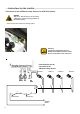
Connection to BCM
For connection to remote control devices
Terminal VII
VII
eBUS
FA
0-10 V
12
VII
Pin 1:
Pin 2:
eBUS (FA) or 0-10V output
(Ground)
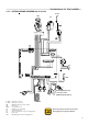
Terminal I
I
12345678910
AF KF / SPF
VF
F9 F8 F6 F5 F3 F2 F1
FBR
I
Pin 4:
Pin 5:
Pin 6: D.H.W.
Pin 7:
Pin 8:
Pin 9:
Pin 10:
Flow sensor, heating circuit 2 (ground)
Flow sensor, heating circuit 2
Storage tank sensor
Storage tank and boiler sensor (ground)
Boiler sensor
Outdoor sensor
Outdoor sensor (ground)
VF
VF
SPF
SPF
KF
AF
AF
Buffer storage tank low sensor
Buf. stor. tank middle sensor / FBR heat. circ. 1 (room sensor)
Buf. stor. tank top sensor / FBR heat. circ. 1 (set value)
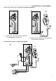
12
V
SPF
F12 F11
VF
Terminal V
V
VF
SPF
Pin 1: C.H. Flow sensor circuit 1 / sensor Multifunction 1
Pin 2: D.H.W. Tank low sensor / sensor Multifunction 2
12
VIII
PT1000
F14 F13
Terminal VIII
F13
F14
Pin 1: Solar sensor 2 / Sensor Multifunction relay 3
Pin 2: 1 / Sensor multifunction relay 4 Solar sensor
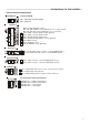
Terminal III
III
123
III
IMP
0-10 V
F17 F15
3
1
FBR
Pin 1:
Pin 2:
FBR heating circuit 2 (room sensor) / 0-10V IN / (to be enabled)
FBR heating circuit 2 (ground)
F15
F17
Pin 3: FBR heating circuit 2 (set value) / Pulse counter for
1234
IX
LH
BUS
Morsetto IX
IX
H
CAN Bus Pin 1 = H (Data communication)
CAN Bus Pin 2 = L (Data communication)
CAN Bus Pin 3 = - (ground, Gnd)
CAN Bus Pin 4 = + (12V supply)
L
-
+