EVE 05 RTN 24 - RTFS 24 CTN 24 F - CTFS 24 F CTN 24 - CTFS 24 00332243 - 3rd edition - 10/2010 INSTALLATION USE AND MAINTENANCE English
General info IMPORTANT This INSTRUCTION MANUAL, which is an integral and indispensable part of the product, must be handed over to the user by the plumbers and must be kept in a safe place for future reference. The manual must be handed over with the boiler should it be sold or transferred. This boiler must be used for the purposes for which it has been designed. Any other use shall be considered incorrect and therefore dangerous.
Users easy guide REMEMBER: • • • • • • Periodically check the water pressure into the boiler. Ascertain to be able to turn OFF the appliance in case of emergency (power, gas and water supply). Make sure to be familiar with the switching ON and OFF and with the temperature adjusting knobs. The user is not allowed to remove the casing and get access to the internal parts of the boiler. Don’t hang dresses, …..etc. to the boiler.
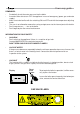
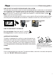
Users easy guide CONTROLS 05 MIN EVE °C MAX MIN MAX ® Display Reset push button Central heating temperature adjusting knob Domestic Hot Water temperature adjusting knob Manometer HOW TO START THE BOILER - Swicth ON the boiler through the external switch. - Check if a room thermostat or a chronothermostat is fitted and set it on heat request.
Users easy guide HOW TO SET THE WATER PRESSURE INTO THE SYSTEM The water pressure into the system has to be checked periodically, in order to be sure of the boiler correct operation. The manometer arrow has to be above 0.8/1 bar when the boiler is switched off or in stand-by position. The boiler lock-out due to lack of water is displayed with the failure code (low Pressure). In order to see this code, once the boiler is in lock-out and the symbol appears, push the reset push-button.
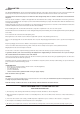
General info - DATA PLATE CE Marking - The CE marking documents that the boilers satisfy: - The essential requirements of the Directive regarding gas appliances (Directive 90/396/CEE) - The essential requirements of the Directive regarding electromagnetic compatibility (Directive 89/336/CEE) The essential requirements of the Efficiency Directive (Directive 92/42/CEE) The essential requirements of the low voltage Directive (Directive 73/23/CEE) ® 1 2 3 4 5 6 7 8 A 9 10 11 12 13 14 B 15 16
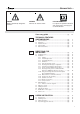
General info For your own safety, observe these safety instructions.: WARNING WARNING Identifies potentially dangerous situations. from risk of electric shock. PLEASE NOTE: User tip for the optimum utilisation and setting of the control(s) plus useful information. User easy guide ................................................................ pag. 1 TECHNICAL FEATURES AND DIMENSIONS ........................................................... pag. 1.1 1.2 1.3 1.4 1.5 2 pag. pag. pag. pag. pag.
Installation info 1 TECHNICAL FEATURES AND DIMENSIONS 1.1 - TECHNICAL FEATURES EVE 05 is a wall hung gas boiler with built-in atmospheric gas burner; it is available in the following versions: EVE 05 RTFS 24 forced draught room sealed boiler, with electronic ignition for heating only; 24 with 24 kW output; C with instantaneous D.H.W. production; for heating only; EVE 05 CTN 24 open boiler, with electronic ignition and instantaneous D.H.W.
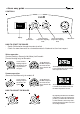
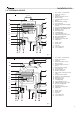
Installation info 1.3 - HYDRAULIC CIRCUIT 1 2 3 4 5 6 7 8 9 10 EVE 05 CTN 24 F 11 10 12 9 11 12 13 14 15 16 17 18 19 20 21 Flow switch - Cold water filter D.H.W. flow restrictor Gas valve D.H.W. temperature sensor Burner nozzles Ionisation/Ignition electrode Burner Bithermal heat exchanger H.L. thermostat Flue gas manifold/down-draught diverter Flue gas anti-spillage thermostat Expansion vessel inflating valve Expansion vessel Automatic air vent Circulating pump C.H.
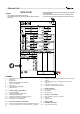
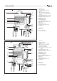
General info 7 6 8 9 5 10 4 3 2 11 12 13 1 14 15 16 18 F G 17 R 7 8 9 10 11 12 13 14 15 16 17 18 Gas valve Burner nozzles Ionisation/Ignition electrode Burner Monotermal heat exchanger Flue gas manifold/down-draught diverter Flue gas anti-spillage thermostat H.L. thermostat Expansion vessel inflating valve Expansion vessel Automatic air vent Circulating pump C.H. temperature sensor Minimum water pressure switch By-pass Boiler drain cock Heating circuit safety valve Filling valve F G R M D.C.
General info EVE 05 CTN 24 12 13 14 15 16 11 10 17 9 8 7 18 6 19 20 5 4 21 3 22 2 1 23 25 24 C F G R M 13 14 12 11 15 16 17 10 18 7 19 6 20 21 5 4 22 3 23 2 24 1 13 14 16 17 18 19 20 21 22 23 24 25 Flow switch - Cold water filter D.H.W. flow restrictor Gas valve D.H.W.
General info 1.4 - OPERATING DATA For the following data: Nozzle - Burner pressure - Diaphragm (where applicable) - Inputs - Gas consumptions refer to pagraph SUITABILITY TO USE OTHER GASES. CTFS 24 RTN 24 CTN 24 F RTFS 24 CTFS 24 F CTN 24 EVE 05 Nominal output kW 24,2 24 24 24,2 24,2 24 Minimum output kW 9,9 10,17 10,17 9,9 9,9 10,17 Actual water efficiency at full load (100%) % 91,34 90,57 90,57 91,34 91,34 90,57 Min.
Installation info 2 DIRECTIONS FOR INSTALLER 2.1 - DIRECTIONS FOR INSTALLER EVE 05 is a gas boiler which must be installed in accordance with the latest regulations or rules in force. For the boiler category, which changes according to the destination country, see page 6. NOTE: Observe the corresponding technical rules and the building supervisory and statutory regulations of the country of final use when installing and operating the system.
Installation info 2.2.2 - POSITIONING THE BOILER MOUNTING JIG FOR BOILER CONNECTIONS 00332145 00332145 120 14.5 78.5 87 110 Every boiler is supplied with special “MOUNTING JIG” with which the pipes for connection to the system, D.H.W. and gas can be positioned when the hydraulic system is being laid out and before the boiler is installed.
Installation info 2.2.3 - ASSEMBLING THE BOILER Before connecting the boiler to the D.H.W. and heating system pipes, carefully clean the pipes to remove all traces of metal resulting from processing and welding operations as well as any oil and grease which could damage the boiler or jeopardize its operation. Unical refuses all liability for injury to persons and animals or damage to property resulting from non-observance of the above. Do not use solvents which could damage the components.
Installation info - - - the sub-horizontal part inside the building must be as short as possible (no more than 1 m); for boilers with vertical discharge, such as boilers EVE 05 TN 24, there must be no more than 2 direction changes; it must receive the discharge from a single boiler; the part going through the wall must be - - protected by a sheath duct; the part of the sheath duct facing the inside of the building must be sealed and the part facing outwards must be open; the final section, on which th
Installation info 2.2.6 - SMOKE DISCARGE AND AIR SUCTION DUCT CONFIGURATION C12, C32, C42, C52, C62, C82 - B22 C12 C32 C42 Boiler designed for connection to horizontal exhaust and suction terminals directly into the atmosphere using coaxial or dual ducts. The distance between the air intake duct and the flue gas outlet duct must be at least 250 mm and both end sections must be located within a 500 mm square.
Installation info 2.2.7 - POSITIONING OF TERMINALS FOR TYPE ‘’C’’ BOILERS either take place through the roof or directly outwards the room they are installed in. The following distances shall be considered for terminals proper positioning: Pursuant to the directives of regulations in force, discharge of forced draught boilers can POSITIONING OF TERMINALS FOR "FORCED DRAUGHT" BOILERS Min. distances in mm.
Installation info 2.2.8 - SMOKE EVACUATION Ø 80 WITH AIR SUCTION FLANGE - Type B22 (see par. 2.2.6) Note: For evacuation system with 80 mm dia. and a lenght between 0.5 m and 4 m, it is necessary to introduce a diaphragm of 42 mm dia. supplied with the boiler in the plastic bag, into the fan outlet adaptor (see fig. 13). The maximum allowed length for a smoke pipe of 80 mm dia. is 20 m, included a wide radium curve and one smoke terminal.
Installation info 2.2.9 - DISCHARGE OF FLUE GAS INTO COAXIAL DUCTS Ø 100/60 mm t Up Type C32 100/60 mm The minimum length of vertical coaxial ducts is 0.5 metres. The maximum allowable length of vertical coaxial ducts is 4 metres excluding the stack (Ø 80/125); for each additional bend the maximum allowable length must be reduced by 1 metre.
Installation info 152 95 100 DIMENSIONS FOR CONNECTION TO COAXIAL FLUE GAS DUCTS fig. 17 2.2.10 - FLUE GAS DISCHARGE AND AIR SUCTION WITH DUAL DUCTS WITH 80 mm DIAMETER It is not allowed to position the 2 terminals in opposite walls, see configuration type C52. NB: The maximum allowable pressure loss, irrespective of the type of installation, must not exceed 50 Pa .
Installation info DIMENSIONS FOR CONNECTION THE AIR INTAKE AND THE FLUE GAS DISCHARGE WITH DUAL DUCTS 123 87 120 90 152 Ø 80 fig. 19 CONFIGURATIONS FOR SEPARATE PIPES (SUCTION AND OUTLET) Ø 80 Example N.1 Primary air suction from perimeter wall and flue gas discharge on roof. > 500 _ Example N.1 Maximum allowable pressure loss: 50 Pa Hmin. = 150 mm fig.
Installation info Example N.2 Primary air suction from perimeter wall and flue gas discharge from the same outside perimeter wall. It is not allowed to position the 2 terminals in opposite walls, Maximum allowable pressure loss: 50 Pa Example N.2 250 min.
Installation info 2.2.12 - CONNECTION TO THE GAS MAINS The supply pipe must have a section which is the same as or greater than the one used in the boiler. Comply with the applicable local installation requirements which shall be considered as having been incorporated in full in this manual. Before opening the internal gas supply system; i.e. before connecting the gas meter, all seals must be checked. If any part of the system is concealed the seals must be checked before the pipes are cove- 2.2.
Installation info DIAGRAM FLOW RATE/MANOMETRIC HEAD AVAILABLE FOR THE CH SYSTEM Manometric Head available in m W.G. EVE 05 RTN 24 - EVE 05 RTFS 24 6,2 6,0 5,8 5,6 5,4 5,2 5,0 4,8 4,6 4,4 4,2 4,0 3,8 3,6 3,4 3,2 3,0 2,8 2,6 2,4 2,2 2,0 1,8 1,6 1,4 1,2 1,0 0,8 0,6 0,4 0,2 0 V3 V2 V1 0 50 100 150 200 250 300 350 400 450 500 550 600 650 700 750 800 850 900 950 1000 1050 1100 1150 1200 1250 1300 1350 1400 Flow rate Q (l/h) Manometric Head available in m W.G.
Installation info 2.2.14 - ELECTICAL CONNECTIONS The electrical connections of EVE 05 are shown in the clause ‘’WIRING DIAGRAMS’’ (par. 2.3 - pag. 29) The boiler must be connected to the mains supply at 230 V - 50 Hz. This connection is to be perfectly done, as foreseen by the IEC and local rules and must be earthed. This fundamental requirement for safety purposes must be checked; in case of doubt, ask for a professionally qualified technician to check the electrical system.
Installation info 2.3 WIRING DIAGRAM Flow switch Rotary flow switch (only for CTN-CTFS) Motor 3 way valve (optional for only heating boiler). Modulating coil ACTUAL WIRING DIAGRAM IONISATION IGNITION ELECTROD MD – MODULATING COIL DK – MINIMUM WATER PRESSURE SR – C.H.
Installation info TABLE OF RESISTANCE VALUES AS A FUNCTION OF THE TEMPERATURE OF THE HEATING SENSOR (SR) AND D.H.W.
Adjustment info 2.6 - ADJUSTING THE BURNER CHIMNEYSWEEPER ACTIVATION OPERATION AT THE MAXIMUM CAPACITY L All the instructions below are for the exclusive use of qualified technicians. All the boilers leave the factory calibrated and tested. If it is necessary to change the calibration following changes in the type of gas or adaptation to the supply network conditions, it is necessary to recalibrate the gas valve. WARNING: During these steps do not draw Domestic Hot Water.
Adjustment info 2.7 - MODIFICATION FOR OTHER GASES The boilers are manufactured for the type of gas specifically required upon order. Any subsequent conversion must be performed by qualified technicians who will use the kits supplied by Unical and perform the conversion and required adjustments for correct preparation of the boiler for use.
Service info 2.8 FAILURE CODES In case of failure the burner is automatically deactivated and the symbol on the display is shown. By pushing the reset button the failure blinking code is shown on the display. Each fault is characterised by a priority level : if different failures are detected at the same time, the code with the highest priority level is shown. The following failure codes are recognised: 2.10.
Service info 2.10.8 Sanitary sensor (priority 8) Description: Sanitary temperature sensor intervention Possible solution: verify the sensor operation and its own connections °C 2.10.9 Heating sensor (priority 9) Description: Heating temperature sensor intervention Possible solution: verify the sensor operation and its own connections °C 2.10.10 Factory parameters (priority 10) Description: Factory parameters alteration Possible solution: with the access code, reset the 13 factory parameters °C 2.10.
Service info USERS' INSTRUCTION 3 3.1 - CONTROL PANEL EVE 05 CTN 24 F - EVE 05 CTN 24 F- EVE 05 CTFS 24 F - EVE 05 CTFS 24 E D B C 05 MIN EVE A °C MAX MIN MAX ® EVE 05 RTN 24 - EVE 05 RTFS 24 E D B A 05 MIN EVE °C MAX MIN MAX ® fig.
Service info Burner in operation This symbol indicates that the burner is in operation, in CH or DHW mode. Reset push button In order to restart the boiler when the lockout symbol is displayed, it will be necessary to push this button. CH mode operation This symbol is present if there is a CH demand. If a contemporary DHW drawing is done, this symbol disappears.
Maintenance info 3.3 ANTI FROST PROTECTION The anti-freeze protection system, which is above described, can not work when, for any reasons, there is no electricity or gas supply. C MIN B MAX MIN MAX The boiler is fitted with an anti-freeze system which is automatically activated when the temperature of the boiler water drops below 6°C: the burner is automatically switched on and the pump started until the temperature of the water in the boiler reaches 16°C. 3.
AG S.P.A. 46033 casteldario - mantova - italia - tel. 0376/57001 (r.a.) - telefax 0376/660556 The Unical declines every responsibility for the possible inaccuracies if owed to errors of transcript or press. Also reserves the right to bring those changes that it will hold necessary to it own products or profits, without jeopardizing its essential characteristics.