Smart-Switch/801 8 Port 10/100Base-TX Switch with 100Base-FX SC/MM ST/MM SC/SM FEP-30109T-C FEP-30109T-T FEP-30109T-C-SM Model shown: FEP-30109T-C 908 Canada Court City of Industry, CA 91748 U.S.A. Phone: 626.964.7873 or 800.346.6668 Fax: 626.964.7880 www.unicomlink.com e-mail: info@unicomlink.com ©UNICOM 2005. UNICOM and “A Network Systems Solution” are trademarks of UNICOM Electric, Inc. All rights reserved. Specifications subject to change without notice. Rev: 09.
Smart-Switch/801 Features Conforms to IEEE 802.3, 802.3u, and 802.
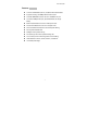
Smart-Switch/801 Package Contents Unpack the contents of the Smart-Switch/801 and verify them against the checklist below. Smart-Switch/801 Fast Ethernet Switch Power Cord Four Rubber Feet RS-232 console management cable User Guide Smart-Switch/801 Rubber Feet Power Cord RS-232 cable User Guide Figure 1-2. Package Contents If any item is missing or damaged, please contact your local dealer for service.
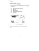
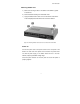
Smart-Switch/801 Hardware Description This section describes the hardware of the Smart-Switch/801. The physical dimensions of the Smart-Switch/801 are 250mm x 132mm x 37mm (L x W x H) Front Panel The Front Panel of the Smart-Switch/801 consists of eight auto-sensing 10/100Mbps Ethernet RJ-45 ports with automatic MDI/MDIX, one 100BaseFX fiber port, and the LED indicators. Smart-Switch/801 with SC Connector Figure 2-2.
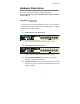
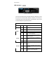
Smart-Switch/801 LED Indicators Figure 2-4. LED Indicators There are three LED Indicators (10/100M, LNK/ACT, FDX/COL) for each UTP port and two LED Indicators (LNK/ACT, FDX/COL) for the fiber port. The following table provides descriptions of the LED status. They provide a real-time indication of systematic operation. UTP Ports LED Power Status Color On Green Power On On Green The port is operating at 100Mbps.
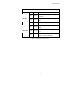
Smart-Switch/801 Fiber Port LED LK /ACT Status Color On Green Blinks Green Off FDX /COL The port is successfully connecting with the device. The port is receiving or transmitting data. No device attached. On Orange Blinks Orange Off Description The port is operating in Full-duplex mode. Collision of Packets occurring within the port. The port is operating in Half-duplex mode or no device attached. Table 2-1.
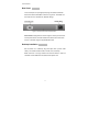
Smart-Switch/801 Rear Panel The Console port and 3-pronged power plugs are located at the Rear Panel of the Smart -Switch/801 as shown in Figure 2-8. This Switch will work with AC in the 100-240V AC, 50-60Hz. Range. Figure 2-5 The Rear Panel of the Smart-Switch/801 Console Port: Configuration is done through the console port connector. This requires a direct connection between the switch and a device such as a PC or terminal using the supplied RS-232 cable.
Smart-Switch/801 Attaching Rubber Feet A_ Make sure mounting surface on the bottom of the Switch is grease and dust free. B_ Remove adhesive backing from the Rubber Feet. C_ Apply the Rubber Feet to each corner on the bottom of the Switch. These footpads protect the Switch from shock and vibration. Figure 2-6. Attaching Rubber Feet to each corner on the bottom of the Switch Power On Connect the power cord to the power socket on the rear panel of the Switch.
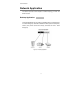
Smart-Switch/801 Network Application This section provides a few samples of network topology in which the Switch is used. Desktop Application The Smart-Switch/801 can be used as a desktop switch, an ideal solution for a small workgroup. Used as a standalone switch, personal computers, servers, and printer servers are directly connected to form a small workgroup. Figure 3-1.
Smart-Switch/801 Segment Application For enterprise networks where large data broadcast are constantly processed, this switch is ideal for connecting workgroups or departments to the corporate backbone. Figure 3-2. Segment Applications Connect PCs, workstations, and servers to each other by connecting these devices directly to the Smart-Switch/801. All devices in this network can communicate with one another as well as with central servers.
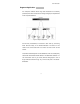
Smart-Switch/801 Smart-Switch/801 Fiber Optic Connection (2km - MM) (30km - SM) 200Mbps Smart-Switch/801 COMPUTER PRINTER SERVER COMPUTER Figure 3-3. Use fiber port (Smart-Switch/801) to extend the distance between workgroups In the above illustration, two Smart-Switch/801 switches are used to connect two small workgroups. By using fiber ports to connect switches, the distance between the two switches can extend up to 2Km (MultiMode) or 30Km (Single Mode fiber).
Smart-Switch/801 Network Configuration This Section explains how to configure VLAN features via a direct connection to the console port on the rear panel of the Smart-Switch/801. This port is a female DB-9 connector. From the main menu of the console program, the user can configure various functions of the switch. Connecting a Terminal or PC to the Console Port Figure 4-1.
Smart-Switch/801 Baud Rate: 9600 bps Data Bits: 8 Parity: none Stop Bit: 1 Flow Control: None Figure 4-2. The settings of communication parameters After you have finished parameter settings, press “OK“. The main console management menu should appear.
Smart-Switch/801 Console Management Console Configuration enables use of a local console terminal or PC to control ports and VLANs on the Smart-Switch/801. Main Menu The Main Menu shows all available switch configuration options. Figure 4-3. The Main Menu of Console Management Per Port Setting From the Main Menu, choose the 1st Item by typing “ 1 “ into the blank. The following screen appears (see fig 4-4).
Smart-Switch/801 Figure 4-4. The default Per Port Setting Figure 4-5. Port statuses to configure Setting VLAN A VLAN (Virtual LAN) is a group of switch ports designated by the switch as belonging to the same broadcast domain. This feature allows workgroups to be defined on the basis of their logical location instead of their physical location. VLANs also help isolate broadcast traffic and increase security.
Smart-Switch/801 Grouping the switch ports into broadcast domains and assigning them to the same VLAN increases performance and network capacity. Moreover, VLAN groups can be modified at any time to add, remove, or change users without any re-cabling. From the Main Menu, choose the second item “ Setting VLAN “ by typing “ 2 “. Follow the VLAN Setup Menu. The switch can support up to nine VLAN groups. Figure 4-6.
Smart-Switch/801 Figure 4-7. The process of creating VLAN group Continue to configure the other ports with another VLAN group. In the following example, we create three VLAN groups (VLAN 1: Port 4, 5, 6; VLAN 2: Port 1, 2, 3, 4; VLAN 3: Port 4, 7, 8, 9) and the 4th port may be connected to an MIS member.
Smart-Switch/801 Troubleshooting This section helps solve the most common problems on the SmartSwitch/801. Incorrect connections Faulty or Loose Cables Look for loose or obviously faulty connections. If they appear to be OK, make sure the connections are snug. If that does not correct the problem, try a different cable. Non-standard cables Non-standard and miswired cables may cause numerous network collisions and other network problem and can seriously impair network performance.
Smart-Switch/801 LED Diagnostic Indicators The Switch status can be easily monitored through panel indicators. If the power indicator does not light when the power cord is plugged in, you may have a problem with AC power outlet or power cord. However, if the Switch powers off once running, Check for loose power connections, power losses, or surges at the AC power outlet. If you still cannot resolve the problem, contact your local dealer for assistance.
Smart-Switch/801 Technical Specifications Standards Compliance IEEE 802.3 10Base-T Ethernet, IEEE 802.3u 100Base-TX/FX Fast Ethernet IEEE 802.
Smart-Switch/801 20
Smart-Switch/801 8 Port 10/100Base-TX Switch with 100Base-FX SC/MM ST/MM SC/SM FEP-30109T-C FEP-30109T-T FEP-30109T-C-SM Model shown: FEP-30109T-C 908 Canada Court City of Industry, CA 91748 U.S.A. Phone: 626.964.7873 or 800.346.6668 Fax: 626.964.7880 www.unicomlink.com e-mail: info@unicomlink.com ©UNICOM 2005. UNICOM and “A Network Systems Solution” are trademarks of UNICOM Electric, Inc. All rights reserved. Specifications subject to change without notice. Rev: 09.