Unicont SPb Ltd Battery control panel BCP-136 Operating manual (136-3-24102013) St. Petersburg 2013 v.3.
Unicont SPb Ltd Operating manual BCP-136 Table of Contents 1. GENERAL .........................................................................................................................3 2. DELIVERY SET ...............................................................................................................3 3. TECHNICAL SPECIFICATIONS .................................................................................4 4. PRINCIPLE OF OPERATION ............................................
Unicont SPb Ltd Operating manual BCP-136 Battery control panel BCP-136 (hereinafter referenced to as battery panel, or panel) is intended for indication of actual battery charging current and voltage, alarming in case of mains power failures and battery discharge. This operating manual describes design and operating principles of the BP, contains instructions for its installation, configuration, operation, warranty and post-warranty maintenance.
Unicont SPb Ltd Operating manual BCP-136 3. Technical specifications Table 1 - Specifications BCP-136 version ДИШУ.468262.001 ДИШУ.468262.001-01 General specifications: Power supply voltage 10.0 ... 36.0VDC Power consumption 3.0 W 2.5 W Galvanic insulation of supply mains Yes Reverse polarity protection Yes Overvoltage protection Number of simultaneously connected batteries Yes (a fuse) 2 pcs.
Unicont SPb Ltd Operating manual BCP-136 4. Principle of operation The battery panel is an electronic device, which consists of the following units: digital processor (CPU), two data transceiving units (RS-422_1, RS-422_2), two battery voltage measurement units (ADC_1.2, ADC_2.2)*, two shunt voltage measurement units (ADC_1.1, ADC_2.
Unicont SPb Ltd Operating manual BCP-136 Battery panel performs the following functions: selection of operating mode of connected battery chargers, indication of actual state (current and voltage) of connected batteries, visual and signal alarming of mains power failure. Panel BCP-136 supports both digital and analog communication interfaces, while panel BCP-136-01 supports digital interface only. Interfaces and external devices to be connected: digital interface (ref. Fig.
Unicont SPb Ltd Operating manual BCP-136 5. Alarms Battery panel is equipped with built-in means of visual and sound alarming intended to alert on emergency conditions (ref. Table 2). Used along with CH-105 or PCH-205, the panel engages these means upon reception of alarms from these devices in digital form (via a digital channel) (ref. CH-105 and PCH-205 operating manuals, section "Alarms"). Table 2.
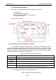
Unicont SPb Ltd Operating manual BCP-136 6. Controls and indicators Battery panel is equipped with the following controls and indicators: control buttons, selected battery LEDs (BAT1/2), alarm LEDs (BAT ALARM 1/2, AC ALARM 1/2), two digital LED indicators. Arrangement of indicators: Fig. 2 Arrangement and general purpose of indicators.
Unicont SPb Ltd Operating manual BCP-136 LED indicator 1 (PORT 1) BAT ALARM 2 (PORT 2) 1 (PORT 1) AC ALARM 2 (PORT 2) Purpose – if a digital interface is used (along with CH-105 or PCH-205), the LED is switched on in case of alarm conditions (ref. CH-105 and PCH205 operating manuals, section "Alarms"), – if an analog interface is used (along with SB-138), the LED is switched on in case of a deviation from specified charge/discharge parameters.
Unicont SPb Ltd Operating manual BCP-136 7. Installation and connection It is recommended to install and connect the battery panel in the following order: a) The panel must be mounted on a horizontal or vertical surface or on a console. Select a place for installation and drill mounting holes in accordance with the outline drawing: guidelines for desktop or bulkhead installation are shown in Fig. 3, guidelines for console installation are shown in Fig. 4. Fig.
Unicont SPb Ltd Operating manual BCP-136 PORT 1 PORT 2 Fig. 4 Console installation of the panel b) Wire connecting cables of external devices. Connect the cables in accordance with the connection diagram taking into account purposes of the connectors: digital interface connection diagram is shown in Fig. 5, Fig. 7; analog interface connection diagram is shown in Fig. 6. Fig.
Unicont SPb Ltd Operating manual BCP-136 Fig. 6 Example of SB-138 connection to the analog interface Note! Prior to connect a battery to the battery panel analog port, ensure that the battery parameters meet the analog interface specifications (ref. section 3).
Unicont SPb Ltd Operating manual BCP-136 Fig.
Unicont SPb Ltd Operating manual BCP-136 Assignment of PORT 1 and PORT 2 connector pins: Table 5. Assignment of PORT 1 and PORT 2 (type DB-15F) connector pins Pin No. Circuit 1 2 3 4 5 6 7 8 9 10 11 12 13 14 15 GROUND NC Rx – Rx + Tx – Tx + Rele Rele NC SHUNT SHUNT + VSUP + VSUP + VSUP – VSUP – Digital interface + – + + + + – – – – – +** +** +** +** Purpose Analog interface* + – – – – – + + – + + +** +** +** +** Power – – – – – – – – – – – +** +** +** +** * – only BCP-136 (ДИШУ.468262.
Unicont SPb Ltd Operating manual BCP-136 d) Configure the battery panel to receive information from external devices: 1 Battery panel operation with digital interface (operation with CH-105 / PCH-205, setting of the battery charging specifications) In order to configure the panel for operation with CH-105 or PCH-205, its main menu is used. Enter the main menu (ref. section 8). By means of BAT1/2 button select the battery, charging specifications are to be set for.
Unicont SPb Ltd Operating manual BCP-136 8. Configuration 8.1 Panel menu In order to configure the battery panel for operation with external devices, its built-in menu is used. The panel menu consists of two sections: the main menu and the section menu. Any of them can be entered when panel operates in the standby (primary) mode (ref. section 8.3). Main menu The main menu of the battery panel is accessible if PCH-205 or CH-105 is connected.
Unicont SPb Ltd Operating manual BCP-136 Fig. 9. General structure of the service BCP-136 menu. Items of the battery panel menu and their functions are briefly described inTable 6 and Table 7. Table 6. Description of the main menu items Menu item Description I Selection of battery charging current (varies in a range of 0.1 – 20.0 A) U Selection of battery charging voltage (varies in a range of 9.0 – 30.
Unicont SPb Ltd Operating manual BCP-136 Note! It is necessary to take into account that charging current and voltage (their maximal and minimal values) are limited in dependence of the connected device type (ref. CH105 and PCH-205 operating manuals). Note! In case the configured parameters do not meet the selected operating mode of the port, the error message ("Err") is shown by the indicator. Table 7 Description of the service menu items. Menu item Description Note UEr_x.
Unicont SPb Ltd Operating manual BCP-136 8.3 Battery panel configuration 8.3.1. Port operating mode configuration (enter the service menu) In order to configure the port for operation with the connected external device type, perform the following actions: press ▲ and ▼ buttons simultaneously and hold them pressed for 5 seconds, until "Prt" message is shown on the left indicator. press ENTER to confirm the selection ("Prt" message is shown on the left indicator).
Unicont SPb Ltd Operating manual BCP-136 press ▲ and ▼ buttons simultaneously and hold them pressed for 5 seconds, until "Prt" message is shown on the left indicator. by means of ▲ and ▼ buttons select "SEt" message on the right indicator. press ENTER to confirm the selection ("SEt" message is shown on the left indicator).
Unicont SPb Ltd Operating manual BCP-136 8.3.8. Test function activation In order to check if the visual and sound elements (LEDs, indicators and the beeper), the panel supports the Test function. In order to activate it, perform the following actions: press MUTE/TEST button and hold it pressed for 3 seconds, until all LEDs are switched on, and the built-in beeper emits continuous sound, release MUTE/TEST button, and the battery panel will return to the primary operating mode. 8.3.9.
Unicont SPb Ltd Operating manual BCP-136 Default configuration Setting PORT operating mode Item Value CH1 dCH CH2 OFF Factory (default) panel settings if the analog channel is activated. A1 parameter (upon activation) A2 parameter (upon activation) Page 22 RSh 100 µΩ Cor - 0.9 A Uh 29.5 V UL 23.5 V Cth OFF ALA Ope RSh 150 µΩ Cor - 0.9 A Uh 29.5 V UL 23.
Unicont SPb Ltd Operating manual BCP-136 9. Transportation and Storage The divice shall be stored in heated space at air temperature of +5 ºС to +35 ºС (maximum values of -55 ºС to +70 ºС), at relative humidity of air not exceeding 95 % at temperature of +25 °C and content of dust, oil, moisture and aggressive admixtures in the air not exceeding the norms envisaged by GOST 12.1.005-88 for the working zone of production areas.
Unicont SPb Ltd 10. Operating manual BCP-136 Recycling Do not recycle the packing of a new product, its parts with defects identified during its operation as well as the overage product as common household waste since they contain materials and raw materials suitable for their recovery. Decommissioned and unused components should be delivered to a specialized waste collection center licensed by local authorities. You can also send the overage equipment to the manufacturer for its further recycling.
Unicont SPb Ltd Operating manual BCP-136 11. Warranty The manufacturer guarantees the unit BCP-136 complies with this manual provided that the operation, transportation and storage conditions are adhered to during the warranty period. The unit’s warranty period expires 24 months from the date of its shipping from the manufacturer’s storehouse.
Unicont SPb Ltd Operating manual BCP-136 12. DATE OF PACKING Battery control panel BCP-136 name of article designation Packed № serial number Unicont SPb Ltd, Russia. Manufacturer according to the requirements of the current technical documentation. post signature clarification of signature year, month, day 13.
Unicont SPb Ltd Operating manual BCP-136 APPENDIX A SAILOR 6081 TO BCP-136 CONNECTION EXAMPLE Connection diagram The device is connected to port 1 or 2. Settings for the first port are listed below. BCP-136 configuration In order to enter the service menu, press ▲ and ▼ buttons simultaneously and hold them pressed for 5 seconds, until "Prt" message is shown on the left indicator.