
User`s manual


User’s Manual 15
Function Jumpers/Connectors
AC’97’ Speaker Output, MIC-In Pin Header J8
5.1Ch Speaker output Pin Header J9
Line-In, CD-In Pin Header J10
SPDIF Pin Header J11
System Power LED LED1
Please double-check the insertion and orientation of the LCD cable
before applying power. Improper installation will result in permanent
damage LCD panel.
Part 1: Onboard Jumpers
JBAT1: CMOS Data Clear (2.0mm)
Pin No. Function
Pin 1-2
Normal (Default)
Pin 2-3
Close for clear CMOS
JP1 (For LVDS2), JP5 (For LVDS1): LVDS Voltage Selector (2.0mm)
Pin No. Function
Pin-1, 2 *
+3.3V
Pin-3, 4
+5V
Pin-5, 6
+12V
Caution: Improper setting will damage LCD panel.
JP7: Pin Header for Case Panel (2.54mm)
Pin No. Function
1(-), 2(+)
HDD active LED
3,6
External Speaker
4,5
Buzzer On/Off
7,8
Hardware Reset Switch
9,10
ATX Power On/Off
11(-),12(+)
Power LED
13,14
Close: Enable WDT function
16 The ENDAT-9401F/H System Board
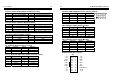
JP2, JP3: RS232 / 422 / 485 Selector for COM2 (2.0mm)
TYPE JP3 (2x3/2mm) JP2 (3x4/2mm)
RS-232 *
1-2 1-2, 4-5, 7-8, 10-11
RS-422
3-4 2-3, 5-6, 8-9, 11-12
RS-485
5-6 2-3, 5-6, 8-9, 11-12
JP4, JP6: COM Port Voltage Selector (2.0mm)
Volta ge +12V(DC) R.I. * +5V(DC)
COM1 (JP4) 1-2 3-4 5-6
COM2 (JP4) 7-8 9-10 11-12
COM3 (JP6) 1-2 3-4 5-6
COM4 (JP6) 7-8 9-10 11-12
Part 2: Onboard connectors
JP2: IR Pin Header (2.54mm)
Pin No. Function Pin No. Function
Pin 1
VCC
Pin 4
GND
Pin 2
N.C
Pin 5
IRTX
Pin 3
IRRX
J4: DIGITAL I/O Pin Header (2.0mm)
Pin No. Function Pin No. Function
1
+5V
2
+5V
3
DIO-I0
4
DIO-O0
5
DIO-I1
6
DIO-O1
7
DIO-I2
8
DIO-O2
9
DIO-I3
10
DIO-O3
11
DIO-I4
12
DIO-O4
13
DIO-I5
14
DIO-O5
15
GND
16
GND
17
DIO-I6
18
DIO-O6
19
DIO-I7
20
DIO-O7
21
+12V
22
+12V