
User`s manual


User’s Manual 17
J8: AC’97 Speaker Output, MIC-In Pin Header (2.54mm)
Pin No. Function Pin No. Function
1
Speaker Output–RIGHT
2
Alternative LFE–Output
3
GND
4
GND
5
GND
6
GND
7
Speaker Output–LEFT
8
First MIC Input/CEN–Output
J9: 5.1Ch Speaker output Pin Header (2.54mm)
Pin No. Function Pin No. Function
1
Surround Output – LEFT
2
Center Output
3
GND
4
GND
5
GND
6
GND
7
Surround Output – RIGHT
8
Low Frequency Effect Output
J10: Line-In, CD-In Pin Header (2.54mm)
Pin No. Function Pin No. Function
1
Line Input – RIGHT
2
CD Input – RIGHT
3
GND
4
GND
5
GND
6
GND
7
Line Input – LEFT
8
CD Input – LEFT
J11: SPDIF Pin Header Connector (2.0mm)
Pin No. Function Pin No. Function
1
+5V
4
GND
2
N.C.
5
SPDIFIN
3
SPDIFOUT
J1: PS/2 Keyboard / Mouse Box Header Connector (2.0mm)
Pin No. Signal (KB) Pin No. Signal (MS)
1
KB Data
2
MS Data
3
KEY
4
KEY
5
GND
6
GND
7
+5V(DC)
8
+5V(DC)
9
KB_CLK
10
MS_CLK
18
The ENDAT-9401F/H System Board
CN3~CN6: COM1~COM4 Box Header (RS-232) (2.54mm)
Pin No. Function Pin No. Function
1
DCD
6
DSR
2
RXD
7
RTS
3
TXD
8
CTS
4
DTR
9
RI
5
GND
10
N.C.
CN3: COM2 Box Header (RS-422Æ 4 Wire)
Pin No. Function Pin No. Function
1
–TXD
6
NA
2
+RXD
7
NA
3
+TXD
8
NA
4
NA
9
–RXD
5
NA
10
N.C.
CN3: COM2 Box Header (RS-485Æ 2 Wire)
Pin No. Function Pin No. Function
1
Data –
6
NA
2
NA
7
NA
3
Data +
8
NA
4
NA
9
NA
5
NA
10
N.C.
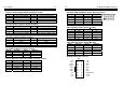
ATXPWR: ATX Power connector
ATX
3.3V 11 1 3.3V
–12V 12 2 3.3V
GND 13 3 GND
PS ON 14 4 +5V
GND 15 5 GND
GND 16 6 +5V
GND 17 7 GND
–5V 18 8 POWER OK
+5V 19 9 5V SB
+5V 20 10 +12V