
User`s manual


User’s Manual 33
3-4. Integrated Peripherals
The IDE hard drive controllers support up to two separate hard drives. These drives
have a master/slave relationship that is determined by the cabling configuration
used to attach them to the controller. Your system supports two IDE controllers--a
primary and a secondary--so you can install up to four separate hard disks.
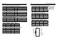
Integrated Peripherals
Item Available Options:
>OnChip IDE Device
Press Enter
>Onboard Device
Press Enter
>SuperIO Device
Press Enter
Onboard Lan Boot ROM Disabled
Onboard Serial Port 3 3E8
Serial Port 3 Use IRQ IRQ5
Onboard Serial Port 4 2E8
Serial Port 4 Use IRQ IRQ10
OnChip IDE Device
Item Available Options:
IDE HDD Block Mode Enabled
IDE DMA transfer access Enabled
On-Chip Primary PCI IDE Enabled
IDE Primary Master PIO Auto
IDE Primary Slave PIO Auto
IDE Primary Master UDMA Auto
IDE Primary Slave UDMA Auto
On-Chip Secondary PCI IDE Enabled
IDE Secondary Master PIO Auto
IDE Secondary Slave PIO Auto
IDE Secondary Master UDMA Auto
IDE Secondary Slave UDMA Auto
*** On-Chip Serial ATA Setting ***
On-Chip Serial ATA Auto
SATA PORT Speed Settings Disabled
PATA IDE Mode Secondary
SATA Port P0,P2 is Primary
34 The ENDAT-9401F/H System Board
Onboard Device
Item Available Options:
USB Controller Enabled
USB 2.0 Controller Enabled
USB Keyboard Support Enabled
AC97 Audio Select Enabled
SuperIO Device
Item Available Options:
POWER ON Function Button ONLY
KB Power ON Password Enter
Hot Key Power ON Ctrl-F1
Onboard Serial Port 1 3F8/IRQ4
Onboard Serial Port 2 2F8/IRQ3
UART Mode Select Normal
RxD, TxD Acitve Hi,Lo
IR Transmission Delay Enabled
UR2 Duplex Mode Half
Use IR Pins IR-Rx2Tx2
Onboard Parallel Port 378/IRQ7
Parallel Port Mode ECP+EPP
EPP Mode Select EPP1.7
ECP Mode Use DMA 3
PWRON After PWR-Fail Off
․Onboard LAN Boot ROM
The default setting is enabled or disabled LAN boot up function.
․
IDE HDD Block Mode
Block mode is also called block transfer, multiple commands, or multiple sectors
read/write.
․IDE Primary Master/Slave PIO and IDE Secondary
Master/Slave PIO
The four IDE PIO (programmed Input/Output) fields let you set a PIO mode (0-4)
for each IDE device that the internal PCI IDE interface supports. Modes 0
through 4 provide successively increased performance. In Auto mode, the
system automatically determines the best mode for each device.