
User`s manual


ENDAT-D2550 USERS MANUAL
UNICORN COMPUTER CORP.
20
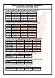
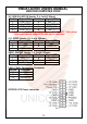
Sample code for output (using Turbo C/C++ 3.0):
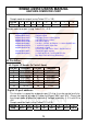
bit No 7 6 5 4 3 2 1 0
Map
NA NA NA NA DIO-O3 DIO-O2 DIO-O1 DIO-O0
Sample code for output (using Turbo C/C++ 3.0)
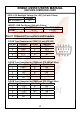
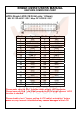
J3 Pin define:
J3: Digital I/O Header (2x7 with 2.0mm)
Pin No. Function Pin No. Function
1 +5V 2 +5V
3 DIO-OUT4 4 DIO-IN4
5 DIO-OUT5 6 DIO-IN5
7 DIO GND 8 DIO GND
9 DIO-OUT6 10 DIO-IN6
11 DIO-OUT7 12 DIO-IN7
13 +3.3V 14 +3.3V
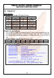
Digital I/O port address:
This function is support by onboard super I/O chip; it can be control easily by
change the register of super I/O chip via I/O port “4Eh” and “4Fh”. Please see
the sample code of below for implement. Voltage tolerance: +/- 5% with 0V to
+5V.
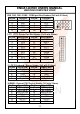
Sample code for input (using Turbo C/C++ 3.0):
bit No 7 6 5 4 3 2 1 0
Map
DIO-I7 DIO-I6 NA NA NA NA DIO-I5 DIO-I4
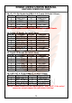
outportb(0x2e,0x87); //Unlock register
outportb(0x2e,0x87); //Unlock register
outportb(0x2e,0x07); //set Logic Device number pointer
outportb(0x2f,0x08); //set Logic Device number
outportb(0x2e,0x30); //set Device Active
outportb(0x2f,0x03); // set Bit 1 =GPIO5 ; 0=Inactive / 1= Active Default: 03h
outportb(0x2e,0xE0); // set GPIO Output / Input Port
outportb(0x2f,0xF0); // 0=Output/ 1=Input
// Bit 0~3 DIO-O0~ DIO3 / Bit4~7 DIO-I0~DIO-I3.
outportb(0x2e,0xE1); //Read DIO-Input register.
outportb(0x2f,0xnm); // n=DIO-I0~DIO-I3 / m=DIO-O0~DIO-O3.
Bit3~Bit4 = DIO-I0~DIO-I3.(Read Only)