ARC246 for BC246T User Manual Version 1.10 2005 BuTel software The Netherlands – all rights reserved www.butelsoftware.com ARC246 Software User Manual 1.
Contents: 1 Introduction and quick start reference 1.1 Software Installation 1.2 Enter registration information 1.3 Connecting the scanner to your PC 1.4 RS232 port setup 1.5 USB information 2 Using and understanding the ARC246 editor: 2.1 Reading data from the scanner 2.2 General hints and tips for using the editor 2.3 How to Build a new system 2.3.1 System parameters 2.3.2 Trunk System parameters 2.3.2.1 Motorola VHF/UHF info 2.3.3 Programming trunk frequencies 2.3.
1: INTRODUCTION: ARC246 is a Windows software package for easy programming and controlling the Uniden BC246T. System requirements: • Windows 98/ME/XP/Win2000/NT • minimum display resolution settings: VGA 800x600 • display must be set to SMALL Fonts • Free serial port com1-com16 or USB to serial converter ARC246 Quick Start Reference: - Install the software (1.1) Enter the registration information (1.2) Connect the scanner to the PC (1.
1.1 Software installation: The ARC246 is available as Internet download or on CD-ROM. Win2000/XP users: You must be logged on as administrator to install and use ARC246. Internet download: The downloaded file contains all the necessary files for installation. Run the exe file and the installer will automatically start. CD ROM: Insert the CDROM; the CDROM has an auto start option that will automatically start the installation process. If the installation process does not start, simply run setup.
Enter registration: Start the software by selecting START _ PROGRAMS _ Butel _ ARC246 _ ARC246 for Uniden BC246T. After the start screen, select HELP _ REGISTER in the menu. Enter the name and key information: the name is case sensitive! No spaces are allowed. The key only contains numbers. The name may contain ‘0’ (=zero) or capital O. 1.3 Connect your scanner: The scanner must be connected to a free serial port. This is normally a 9-pin connector at the back of your PC.
1.4: Getting started: RS232 communication setup After installation of the software you must check and set the software settings for RS232 communication. Start the software and select: BC246T _ RS232 setup from the menu. The software has an auto detect option. If you know the settings for the serial communications port and baud-rate you can manually set them. Select OK and the software will store your settings. The software remembers these settings.
After setting up the serial communication you can check the connection. From the main menu select: BC246T _ Virtual Control. After a few seconds the Virtual control panel should show the contents of the scanner display. Below is an example (your ‘display’ will look different): ARC246 Software User Manual 1.
1.5: USB information Uniden scanners use a standard RS232 port for computer programming and control. Uniden scanners do not have a USB port available. Therefore ARC246 is developed to support standard serial comports. For laptop PC's that do not have a serial port we advise to use a PCMCIA serial port extender card. Several manufacturers also sell serial<>USB converters. These converters create a virtual software RS232 port and can work very unreliably.
2: Using and understanding the memory channel editor: ARC246 includes the most versatile memory editor available on the market. Unlike other software packages you can use ARC246 without a scanner connected. The main editor screen layout is divided into two panes, the left pane is called the ‘system browser’, the right pane is called the ‘channel editor’. For your convenience Windows style toolbars and right mouse click menu’s are available.
The top section has a standard Windows MENU bar and a Toolbar. Most options found in the menu also have a ‘shortcut’ in the toolbar. If the mouse is moved over a toolbar button a help text is shown giving a brief description of that button. The editor bar changes as you move the mouse in the editor grid, if you click on a column the editor bar will show the right edit options. You can edit data both in the editor bar or directly in the editor grid.
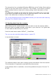
You can read all systems or selected systems. Make your selection in the list box by clicking the selection boxes. For your convenience, Select All and Unselect All buttons are available. In this window you can also delete systems from your scanner. Add System’s option: when this box is checked, the Arc246 browser will not be cleared and all systems you read from the scanner are added into the browser. Important: ARC246 can handle systems with the same ‘systemname’.
2.3 Build a new system: To build a new system select ‘FILE _ NEW’, this will add a new system to the systembrowser, in this sample screenshot New System 2 was added. ARC246 Software User Manual 1.
2.3.1 System Parameters Click the ‘New System 2’ line in the systembrowser to open the system parameter editor: First enter a unique name in the ‘System Name’ box. Select the System Type, depending on the systemtype, extra tabs are shown to setup trunk system parameters. Website: enter a website with information about this system. Pressing ‘Check Site’ will open the website. This website link is stored in your system file. System options: set the system options, refer to BC246T user manual for information.
For your convenience, the system browser shows unique icons per system type: In this screenshot a conventional, a Motorola, a Edacs and a LTR systems are loaded. ARC246 Software User Manual 1.
2.3.2 Trunk system Parameters For every trunk system, several parameters can be set: Refer to BC246T user manual for more information. General: Motorola VHF/UHF: you must program a base, offset and step frequency (see next page). Motorola Type 1: for a Motorola type 1 a fleetmap must be selected or a custom fleetmap must be build. For a TYPE 1 system it is very important that the trunk system is setup correctly before any trunk id’s are uploaded to your scanner.
2.3.2.1 Motorola VHF/UHF systems: Explanation of base/step/offset parameters: For a type 2 VHF or type 2 UHF you must program base/step/offset parameters. For properly tracking a type 2 VHF/UHF system, the scanner needs channel number information. The tracking process is controlled by sending channel numbers instead of frequencies.
2.3.3 Trunk frequencies Click the Trunk frequencies tab to enter or paste trunk frequencies: The Name column is NOT sent to the scanner, this information is only stored in system files. For Edacs and LT systems the LCN number must be entered. Motorola systems do not use LCN information. ARC246 has a powerful option to ‘paste’ frequencies from popular websites like www.radioreference.com , see section 2.3.4 ARC246 Software User Manual 1.
2.3.4 Pasting frequencies from a website: While setting up trunk systems, you have probably spend a lot of time typing over frequency lists. ARC246 has a new paste option that will do this for you. First locate a website with trunk frequency information, in the sample we use a trunk system website found at: http://www.radioreference.com/modules.php?name=TRSDB&sid=3352 We want to copy the frequencies from this website into ARC246. ARC246 Software User Manual 1.
The first step is to highlight the frequencies at this website by holding down the left mouse button, then select CTRL-C or Edit _ Copy in your browser. (there are 24 frequencies used in this system) ARC246 Software User Manual 1.
Return to ARC246 and in the Trunk frequency editor click the right mouse button and select ‘paste frequencies’ and all frequencies are pasted in the grid: ARC246 Software User Manual 1.
2.3.5 Setting Up groups in a system After a new system is created you can setup the groups that belong to that system. In the systembrowser select ‘Edit groups’ from the right mouse button menu: In this window you setup Groups: First select the groups that you want to add to the system. This is done by clicking the ‘active’ box. A system can store a maximum of 20 groups. Important: Only data of ‘active’ groups is stored in a systemfile. If you disable groups, the data from that group is lost.
2.3.6 Adding and Deleting groups from a system: Add a group to existing system: Once a system is created you can also add new groups using the system browsers right mouse button menu. ( Add Group). A system can only hold 20 groups. Systems can also be added in the Group Editor ( Setup _ Groups ), click the active option for groups you want to add to a system. Delete a Group from a system: Open the Group Editor ( Setup _ Groups ) and uncheck the ‘active’ option for groups you want to remove from a system.
2.3.7 QuickSave: Systems are stored in separate files. To avoid that you need to manually save all systems, a QuickSave option was developed. A system file can have a different filename than the systemname! In the ‘system’ editor the actual filename and location is shown. When you select QuickSave the software first checks if a filename already exists in the software (shown in system editor screen). If there is no filename stored, the software uses the systemname as filename (only first 16 characters).
2.4 Default data: When you enter a frequency or ID and you press ENTER the other cells of that line are automatically programmed depending on your custom settings (default channel data). You can customize the default data: select SETUP _ SETUP DEFAULT DATA. A new window is shown: In this window you set the default data that is put in the grid when you press enter. All parameters that have the check box selected will be put in the grid.
2.6 EasyFill EasyFill is a simple but powerful option that lets you program data in a range of channels with only a few mouse clicks. Additionally you can use EasyFill for quickly program a range of frequencies in a memory bank so you can use a memory as a search bank. Select EasyFill from the Options menu or use the EasyFill toolbar button to display the EasyFill window: In the top frame the channel range is selected. DEFAULT will set the start and end channel of the selected bank.
Fill series: for the TAG option you can also set the fill series option. Fill series will search for a number in the tag and use that number to ‘calculate’ the tags in the selected channel range. Example: in the tag box the tag is set to ‘Police 1’. The channel range is set to 1-100. If fill series is selected, the software will automatically program ‘Police 1’ in channel 1, ‘Police 2’ in channel 2, ‘Police 3’ in channel 3 etc. See also section 2.9. The number of characters of the tag box is shown in blue.
2.7 Using the clipboard In the memory editor grid you can use the standard Windows clipboard options. In the toolbar shortcuts are available for cut, copy and paste options. You can also use the keyboard shortcuts CTRL C, CTRL X and CTRL V. Use these options to paste data from other applications like Excel. An additional clipboard option is available that will automatically select entire lines (Cut line, copy line and paste line).
2.8.1 Copy/Move/Swap Memory Channels: The ‘from’ and ‘to’ list boxes will automatically display the channel number, frequency and tag. Channels that are empty (no frequency programmed) are indicated as Empty. Current Bank: copy/move/swap channels in the active bank All Banks: copy/move/swap channels in all Banks 2.8.2 Copy/Move/Swap groups within a system: Use this window to copy/move/swap entire memory groups. The ‘Include Bank Tag’ options will also copy/move/swap the bankname.
2.8.3 Copy/paste groups between systems In the systembrowser you can copy/paste groups. Click on the group you want to copy and select the right mouse button. Select ‘Copy Group’ Next select the system where you want to paste the data, and select ‘Paste group’ in the right click menu. IMPORTANT: you can only copy/paste groups that are the same system type. So for example you can not copy a Motorola group into an Edacs system etc. 2.8.4 Copy/paste systems In the systembrowser you can copy/paste systems.
2.9 Fill Down / Fill Series The Fill down and fill series options are used to copy the same data into a range of channels. Fill series will auto calculate ascending numbers in text tags (see examples below) This example will show fill down: Channel 10 contains Trunk=OFF, Delay Time = 4 seconds and Record =ON We want to copy this data to channels 11-20; first you must highlight the channel range: Now select the FILL DOWN option: ARC246 Software User Manual 1.
The software will automatically fill the selected range, using the data at the top of the selected range. Fill Series: Fill series only works in the tag column. It will look for number information in the tag and auto increase the number in ascending channels. Example: Channel 10 contains the tag ‘UHF Channel 431’: Highlight the channels where you want to copy the data to: Now select the FILL SERIES option and ARC246 auto calculates the new tags: ARC246 Software User Manual 1.
2.10 Other Options: PL/DPL Column : You can directly enter a CTCSS or DCS tone. The software will auto correct your entry. Tones that are entered and have a decimal are considered CTCSS tones. Tones without a decimal are DCS tones. Tips: You can scroll the list with subtones by using the - and + keys. Shift _ spacebar will scroll down. ARC246 Software User Manual 1.
2.11 Understanding how data is stored in ARC246 In ARC246 data is stored in a system file or in a profile file. System File: Stores a single system with all related parameters: - system settings, including systemname, systemtype, QuickKey and website. group settings channel data (either frequencies or trunk id’s and related channel parameters) Profiles: A profile stores a list of system filenames. When you open a profile, all system files that are stored in that profile are opened.
2.11.1 Viewing a Profile / Profile Creator: The Profile Creator makes it easy to create new profile, a profile is a collection of system files. A systemfile can be used in more than one system. Important: Since a profile only stores the location of a systemfile and NOT the actual data, be careful when you move mem files into different folders. Use the drive and folder navigation to locate system files (.mem) files. The lower part is the contents of the profile.
‘Import All’ will import all ARC246 mem files from the active folder (maximum is 200 files). You can also modify existing profiles, use the Open Existing PFL button to load existing profiles. Clean Up: if system files were moved to different folders you can use this button to clean up the profile. This option will check all files in the profile are still at their stored location. If they are moved, that system file is removed from the profile. ARC246 Software User Manual 1.
2.12 Organizing QuickKeys The BC246T uses QuickKeys to ‘combine’ systems so they can be scanned together. Also groups within a system can be assigned to a QuickKey. QuickKeys are numbers 1-9 and 0. In the systembrowser you will find the QuickKey Menu with powerful options to display, print and organize your QuickKeys.
Within a system you can lockout groups, these groups will not be scanned even when the assigned Quickkey is selected. To indicate that groups have the lockout flag set a ‘L’ is displayed in the systembrowser: In this screenshot you can see that the ‘GMRS channels’ group has been assigned to QuickKey 2 but it has the Lockout parameter set so will not be scanned. The group ‘CB channels’ has not been assigned to a QuickKey but has the Lockout flag set. Group QuickKeys are set in the Group Editor.
2.12.1 QuickKey Overview: Click the ‘Overview’ button in the Quickkeys menu to show the Quickview Overview: This window will show per quickkey the systems or groups that are assigned to that quickkey: In the screenshot above you can see by Quickkey which systems are assigned to one of the quickkeys. You can also view the group quickkeys, in the ‘select’ dropdown list, select the system you want to see: You can simply use mouse drag and drop to move systems/groups into quickkeys.
2.13: Uploading data into the scanner: From the main menu select: BC246T _ Send Data Tip: you can also use the toolbar button or press F6. Empty channels are NOT sent to your BC246T. A new window is shown: You can upload ‘All Systems’ or ‘Selected’ systems. Make your selection in the system overview. Select All and Unselect All options are available. Upload options: ‘Clear All Systems first’ : this option will erase all systems that are stored in your BC246.
2.14 Import/Export data: ARC246 can import data from various sources: - import using the clipboard: you can easily copy/paste data from Excel or other database software that supports the clipboard - import frequencies from text/html/csv files. Use the WebCatcher option to import from these files.
2.15 Modify the software bandplan. The BC246T has a build in Automode bandplan, this means that when you enter a frequency, the scanner will select mode and step from a preset list (see page 10-11 of BC246T user manual). ARC246 also uses this bandplan, by default mode and step of new frequencies are set to Auto. You can change this behaviour. In the systembrowser click on a conventional group. In the menu select SETUP _ BANDPLAN: Here you can modify the behaviour for a frequency range.
3.1 Using WebCatcher for importing frequencies from internet website: ARC246 can very easily import frequencies from any website. • • • • • • • • Start the ARC246 software Open you internet browser and open a website displaying frequencies you want to import (example: http://www.trunktracker.
• ARC automatically removes duplicate frequencies: • For import into the memory table you must transfer the frequencies to the right list. Finally you select in what bank and at what channel you like to import the data. • • Press "EXPORT TO TABLE" button and frequencies are ready for upload! ARC246 Software User Manual 1.
• WebCatcher works with ANY website, the website shown above is only an example. Here is the result of WebCatcher (screenshot was taken from ARC250): ARC246 Software User Manual 1.
3.2 TrunkWebCatcher TrunkWebCatcher is a small but useful utility for importing trunk data from websites. You can import frequencies, trunk id’s and descriptions from websites in seconds! You can also modify data before you export or save. TrunkWebCatcher will convert selected text from a website (using the clipboard) into a grid. Depending on the filters you define, the data in the grid can be refined.
Columns setting: By default the software assumes the first part of the lines that are imported, are trunk id’s. If the data you copy has more columns, you can increase this setting so data is split into more columns. The space is used as separator. Just play with this setting to get the best result. Columns can always be combined or removed.
Filters: Because trunk id’s are normally just ‘numbers’, WebCatcher can not tell the difference between an id and other data. Therefore you must use filters. Experiment with these filters. As long as data is not copied back onto the clipboard, you can always go back to the original data by using the ‘Import from Clipboard’ option. Follow these 3 basic steps: 1: Import From Clipboard To Clipboard > 2: Filter data > 3: Copy Selection Once data is copied onto the clipboard, simply paste in ARC246.
+ Line must contain number of at least x digits: example when this is set to 3, a line containing 12-04-04 (could be a date) will be removed. Look at the website and increase this number if possible to get better results for Motorola systems. + Number must be dividable by 16: Most Motorola typ2 trunk id’s are dividable by 16. Check this option to improve results for mot 2 id’s. + Remove String: this option scans the whole grid and simply removes the string you enter.
Detailed Description and sample how to use the TrunkWebCatcher: Screen copy of a website showing trunk id’s / tags we want to import: (data source: Michigan State Police trunk system, at www.radiorefence.com) We want to import the trunk id’s and text from this website, first step is to highlight the section we want to import, you do this by holding down the left mouse button and move it over the section, your web browser will highlight the selection: ARC246 Software User Manual 1.
Now in your web browser you select EDIT _ COPY or simple press CTRL C , this will copy the selected text to the clipboard. ARC246 Software User Manual 1.
Go to the TrunkWebCatcher and select ‘Import from Clipboard’ : The text that you just highlighted is copied into the grid. Since the data at the website was divided into several columns, increase the ‘Split in Columns’ option to 4. ARC246 Software User Manual 1.
You will now see that the software divided the selected text back into the original columns: In this particular case the website already has a column called ‘Display’ . Because your scanner can only show a limited number of characters for the tag, the data from this column can be used to import into ARC246. The grid also shows a ‘long’ description but scanners can not store that. You can save the file with the long description to csv format for later reference. ARC246 Software User Manual 1.
You can use filters to remove unwanted data, although the grid can be easily used to copy data into your scanner software. In this example lines without numbers were removed: ARC246 Software User Manual 1.
Final step is to highlight area’s in the grid that we want pasted into other software, in this example we highlighted the column with trunk id’s and when you click ‘Copy Selection to Clipboard’ you can paste that into ARC246. ARC246 Software User Manual 1.
You can do the same for the display column: ARC246 Software User Manual 1.
Finally there may be websites that do not show descriptions that will fit your scanner, here is an example of using TrunkWebCatcher option to make shorter descriptions: In the Description column you see for example ‘Statewide District’ , you can replace this by ‘STW DIS’ or what you like: ARC246 Software User Manual 1.
And clicking Apply will give you: ARC246 Software User Manual 1.
4 Configuration parameters: From the main menu select ‘VIEW _ Configuration Editor’. If this option is not shown, click on a system in the system browser. You can edit BC246 configuration parameters like general settings, custom search ranges and SAME settings for WX alert. The current version of ARC246 does NOT save configuration data. If you want to edit these parameters read them from the scanner, modify them and send them back to the scanner.
5 Virtual Control ARC246 includes a virtual control option. Virtual control shows real-time scanner display data and you can operate the scanner from your PC keyboard using smart shortcuts. The history log will show recent activity ** (see next page for details). ** The log option in V1.01/1.02 may store false hits. The logger option will be improved in future versions of ARC246.
Information logged in the history log grid: Conventional Scan Mode : - System and Group Frequency Channel Name Time/Date Hitcount* IMPORTANT: In Conventional Scan Mode, Virtual Control will only log subtones that are found in sub tone search mode. Subtones programmed in channels are not logged, this is a limitation of the BC246T.
5.
6 General information and troubleshooting 6.1 Troubleshooting communication problems In case of communication problems you can use the information in this section to troubleshoot communication problems. 6.1.1 Set/Check scanner communication settings: Switch on your scanner, verify the scanner is enabled for RS232 serial communication: Press MENU , select ‘Xfer Information’ ‘PC Control’ and select 57600 and press E to store this setting. 6.1.2 Check your cable The BC246T comes with a special serial cable.
6.2 Revision history: ARC246 V1.00: release January 2005 ARC246 V1.01: release February 2005: New options/problems fixed: • • • • • • • • • • • • • • • • • • • • • • Modify software bandplan Better logging in conv.
ARC246 V1.100: release August 2005 • • • Included RadioReference database reader New option to set preset Quickkeys Fixed misc. small bugs ARC246 Software User Manual 1.
7 FCC lookup ARC246 has a build FCC frequency lookup utility. You can directly search the online FCC database, press F3 to open the search window. First select a State and then enter the frequency. You can also directly check frequency data from the grid: - click on the frequency you want to check, in this example 476.5375, the frequency is shown above the grid in the editor bar. Press F3, the FCC lookup window is shown and the frequency is copied to that window.
And here is the result of the FCC search: ARC246 Software User Manual 1.
8 RadioReference Database import With ARC246 you can import trunk system data directly from www.radioreference.com , the largest scanner database in the world. For information about the database check out: http://www.radioreference.com/modules.php?name=RR IMPORTANT: To use the Radioreference import option you must sign up as a member and make a donation to Radioreference.com. In ARC246 select ‘INTERNET _ RADIOREFERENCE’ and the import window is shown: Enter your Username and password and press ‘CONNECT’.
To import data, select at least one sites/System frequencies and one group with Trunk ID’s. Next press ‘Create System’ and system will be added to your systembrowser. Control Ch. Only: when you select this option, the software will only import control channel frequencies and the software will automatically enable the ‘Control Channel Only’ mode for the selected system. If the radiorefence.com import option does not work, check the following: • • • • make sure your username/password is valid. Go to www.