Repair GH™ 130, GH 200, GH 230, GH 300 Hydraulic Sprayers 311797B - Use with Architectural Coatings and Paints 3300 psi (2.8 MPa, 228 bar) Maximum Working Pressure List of models provided on page 2. Important Safety Instructions. Read all warnings and instructions in this manual. Save these instructions. Contact Graco Customer Service, your local Graco distributor or our website: www.graco.com, to obtain a manual in your language. ti5380a English Graco Inc. P.O.
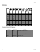
Models Models GH130 GH200 GH230 GH300 120 Vac 60 Hz 253709 253957 253959 253980 ✔ ✔ ✔ ✔ 253960 253962 253963 253981 255095 ETL/CSA/UL 120 Vac 60 Hz ✔ ✔ ✔ ✔ ✔ ✔ ✔ ✔ ✔ ✔ ✔ ✔ ✔ ✔ ✔ ✔ 253964 253965 253966 253982 253967 253968 ✔ ✔ ✔ ✔ ✔ ✔ Electric Motor Kit Options Kit Number 2 Sprayer Model Description 288474 GH130 120VAC, 60Hz, 20A, CAS/UL approved 288473 GH130 120VAC, 60Hz, 15A 248950 GH200/GH230 120VAC, 60Hz, 20A, CSA/UL approved 248949 GH200/GH230 120 VAC, 60Hz, 15A 248946 E
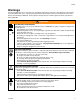
Models Warnings The following Warnings are for the setup, use, grounding, maintenance and repair of this equipment. The exclamation point symbol alerts you to a general warning and the hazard symbols refer to procedure-specific risks. Refer back to these Warnings. Additional, product-specific warnings may be found throughout the body of this manual where applicable. WARNING FIRE AND EXPLOSION HAZARD Flammable fumes, such as solvent and paint fumes, in work area can ignite or explode.
Models WARNING MOVING PARTS HAZARD Moving parts can pinch or amputate fingers and other body parts. • Keep clear of moving parts. • Do not operate equipment with protective guards or covers removed. • Pressurized equipment can start without warning. Before checking, moving, or servicing equipment, follow the Pressure Relief Procedure in this manual. Disconnect power or air supply. EQUIPMENT MISUSE HAZARD Misuse can cause death or serious injury.
Component Identification Component Identification 2. 1. 3. off on bar/MPa PSI 12. 4. ti9167a 11. ti9126a ti8714a 5. 10. F OF ON 6. ti9166a 13. ti8691a 9. 8. 7. ti5381b ti8844a 311797B Item No.
General Repair Information General Repair Information SAE O-Ring Installation 1. Unscrew lock nut to touch fitting. To reduce risk of serious injury, do not touch moving parts with fingers or tools while testing repair. Shut off sprayer when repairing. Install all covers, gaskets, screws and washers before operating sprayer 1. Keep all screws, nuts, washers, gaskets, and electrical fittings removed during repair procedures. These parts are not normally provided with replacement assemblies. 2.
Maintenance Maintenance DAILY: Check and fill the gas tank. DAILY: Check that displacement pump is tight. Pressure Relief Procedure The system pressure must be manually relieved to prevent the system from starting or spraying accidentally. Fluid under high pressure can be injected through the skin and cause serious injury.
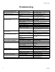
Troubleshooting Troubleshooting PROBLEM Gas engine pulls hard (won't start) Gas engine does not start Gas engine doesn't work properly Gas engine operates, but displacement pump doesn't operate Displacement pump operates, but output is low on upstroke Displacement pump operates but output is low on downstroke and/or on both strokes Paint leaks and runs over side of wetcup Excessive leakage around hydraulic motor piston rod wiper Fluid delivery is low CAUSE SOLUTION Hydraulic pressure is too high Tur
Notes Notes 311797B 9
Hydraulic Pump Hydraulic Pump (Figure 2) Removal Let hydraulic system cool before beginning service. 1. Relieve pressure, page 7. 2. Place drip pan or rags under sprayer to catch hydraulic oil that leaks out during repair. 3. Remove drain plug (2) and oil filter (227) and allow hydraulic oil to drain. 4. Fig. 2. Disconnect suction tube (114). 5. Disconnect pump (111), page 15. 6. Remove screw (172), nut (173) and belt guard (117). 7. Raise motor and remove belt (44). 8.
Hydraulic Pump 222 227 221 266 225 226 220 173 96 44 211 117 276 209 172 277 212 207 206 111 176 114 2 203 ti8821b FIG.
Fan Belt Fan Belt (Figure 3) Removal 1. 2. 3. 4. 5. Installation 1. Thread belt (44) around drive pulley (43) and fan pulley (96). 2. Let engine (119) down to put tension on belt. 3. Rotate belt guard (117) down. 4. Tighten belt guard knob (55). Relieve pressure, page 7. Loosen belt guard knob (55). Rotate belt guard (117) up. Lift engine (119) up to remove tension on belt (44). Remove belt from pulley (43) and fan pulley (96). 117 44 ti8815a 119 43 96 ti8814a ti8816a 55 FIG.
Engine Engine (Figure 4) Removal Installation NOTE: All service to the engine must be performed by an authorized HONDA dealer. 1. Install rocker plate (99), dampeners (153) and washers (154) on engine (119) with four screws (23), washers (7) and nuts (24); torque to 125 in-lb (14.1 N·m). 2. Install engine and rocker plate (99) on sprayer. 3. Swing motor retainer bracket (204) in. Tighten motor nut (205). 4. Install Fan Belt, page 10. 1. Relieve pressure, page 7. 2. Remove Fan Belt, page 10. 3.
Hydraulic Motor Rebuild Hydraulic Motor Rebuild (Figure 5) Removal 1. Relieve pressure, page 7. 2. Place drip pan or rags under sprayer to catch hydraulic oil that leaks out during repair. 3. GH130 Models: - Follow Steps 2-5 of pump removal instructions, page 17. GH200, GH230, GH300 Models: - Follow Steps 4-8 of pump removal instructions, page 18. 4. Remove hydraulic lines (271, 288) from fittings (266) at top left and right side of hydraulic motor. 5. Loosen jam nut (264). 6.
266 265 test hole 288 271 ti8817A 261 258 260 259 257 264 ti8819a 263 ti8818a FIG.
Hydraulic Oil/Filter Change Hydraulic Oil/Filter Change (Figure 6) Removal 1. Relieve pressure, page 7. 2. Place drip pan or rags under sprayer to catch hydraulic oil that drains out. 3. Remove drain plug (2). page 26. Allow hydraulic oil to drain. 4. Unscrew filter (227) slowly - oil runs into groove and drains out rear. Installation 1. Install drain plug (2) and oil filter (227). Tighten oil filter 3/4 turn after gasket contacts base. 2.
Displacement Pump Displacement Pump GH130 Only (Figures 7-12) See manual 311845 for pump repair instructions Installation Removal 1. Flush pump. 2. Relieve pressure, page 7. If pin (92) works loose, parts could break off and project through the air, resulting in serious injury or property damage. Make sure pin is properly installed. 3. (Fig. 7) Remove suction tube (114) and paint hose (63) (remove at swivel end).
Displacement Pump ProConnect Displacement Pump ProConnect GH200/230/300 Only (Figures 13-27) See pump manual 311845 for pump repair. Removal 5. (Fig. 15) Slide coupler cover (193) up to fully expose rod couplers (179). 247 193 1. Flush pump. 2. Relieve pressure, page 7. 3. (Fig. 13) Remove suction hose (114). 179 ti8829a FIG. 15 6. (Fig. 16) Remove rod couplers (179). 179 ti8827a FIG. 13 179 4. (Fig. 14) Remove paint hose fitting (190) and paint hose (63) from pump fitting. 190 FIG.
Displacement Pump ProConnect Installation CAUTION Support pump with your hand before opening t-handle. 1. (Fig. 20) If needed, place pump rod in adjustment casting and pull pump to lengthen rod. 8. (Fig. 18) Open clamp (247). ti8834a FIG. 20 2. (Fig. 21) Install pump (111) in sprayer. ti8833a FIG. 18 9. (Fig. 19) Remove pump (111) from unit. 111 111 ti8959a FIG. 21 FIG. 19 ti8832a 3. (Fig. 22) Close clamp (247) around pump (111) and push it closed. 247 Adjustment hole ti8958a FIG.
Displacement Pump ProConnect 4. (Fig. 23) Install pin. 6. (Fig. 25) Slide couple cover (193) down over rod couplers (179). 193 179 ti8957a FIG. 23 ti8955a 5. (Fig. 24) Slide coupler cover (193) up to expose pump rod. Install rod couplers (179) over rod. FIG. 25 7. (Fig. 26) Open clamp and align pump outlet with hose fitting (190). Install paint hose fitting (190) and paint hose (63) to pump connection, close clamp. 190 193 179 179 ti8956a 63 FIG. 24 ti8954a FIG. 26 8. (Fig.
Notes Notes 311797B 21
Parts Parts All Sprayers 234 233 232 228 231 121 63 103 150c 227 112 75 79 150b 150d 35 228 230 150a 150e 216 150f 182 132 229 217 91 215 213 81 58 62 150g 199 57 59 60 61 GH130 Model 200 39 54 180 116 70 174 200 ti8822a 22 311797B
Parts Parts List - All Sprayers Ref Ref 35 39 Part 112827 119420 119408 54 156306 111841 57 15C780 58 15C972 59 224807 60 235014 61◆ 15E022 62◆ 111699 63 243814 70 120211 15B563 75 15J645 188350 79▲ 189246 81 192027 91▲ 194317 103 288732 112 248818 116 288169 248815 121 116756 132 109032 150 245103 150a★ 193710 150b★ 193709 150c★ 114797 311797B Description Qty BUTTON,snap 2 WHEEL,pneumatic, GH130 & 200 2 WHEEl, pneumatic, GH230 & 300 2 WASHER,flat, GH130 & 200 2 WASHER, plain, 5/8, GH230 & 300 2 HANDLE,
Parts Drawing - Engines Parts Drawing - Engines GH130, 200, 230 88 119 126 106 133 43 24 7 126 154 153 34 99 30 154 23 88 GH300 119 161 24 126 133 7 43 106 154 153 160 34 30 162 99 154 23 ti8813a 24 311797B
Parts Drawing - Engines Ref 7 23 24 30 34 43 88▲ 99 Part 100023 100132 113664 106212 110838 101566 108842 116645 112717 119438 116908 119401 194126 15F157 15E583 106 15B314 15E586 119* 120590 802264 311797B Description Qty WASHER,flat, GH130, 200 & 230 4 WASHER, flat, GH300 4 SCREW,cap,hex hd, GH130, 200 & 4 230 SCHREW, cap, hex hd, GH300 4 NUT,lock, GH130, 200 & 230 4 NUT, lock, GH300 4 SCREW,cap,hex hd, GH130, 200 & 1 230 SCREW, cap, hex hd, GH300 1 WASHER,GH130, 200 & 230 1 WASHER, GH300 1 PULLEY,
Parts Drawing - All Sprayers Parts Drawing - All Sprayers 224 223 225 222 221 226 56 96 220 117 211 176 148 214 212 44 219 287 173 51 284 139 101 209 55 172 48 184 277 204 200 207 170 206 115 144 203 55 201 2 ti8823a 26 311797B
Parts Drawing - All Sprayers Parts List - All Sprayers Ref 2 44 48 51 55 56 96 99 Part 101754 119433 119432 803298 117284 15D862 154594 15E410 15F157 15E583 101▲ 15K431 15K433 15K435 15K437 115 288261 288393 117 288734 248973 139▲ 144▲ 148 170 172 173 198492 15K440 115477 102040 119434 116969 311797B Description Qty PLUG 1 BELT, GH130, 200, 230 1 BELT, GH300 1 SCREW,hex head 2 GRILL,fan guard 1 NUT,hand 2 O-RING 1 PULLEY,fan 1 BRACKET,mounting, engine, 1 GH130, 200 & 230 BRACKET, mounting, engine, 1
Parts Drawing - All Sprayers Parts Drawing - All Sprayers GH130 GH200/230/300 120 103 86 124 92 193 122 194 188 114 179 111 187 189 89 186 63 188 110 111 199 190 195 196 114 63 198 197 ti8820a 114 28 311797B
Parts Drawing - All Sprayers Parts List - All Sprayers Ref 63 86 89 92 103 110 111 Part 243814 193031 15D000 15J141 288732 241920 288466 288467 288468 114 288251 288252 116551 162485 120 122 311797B Description Qty HOSE,coupled 1 NUT, retaining, GH130 1 CLIP,drain line 1 PIN, pump, GH130 1 KIT, drain hose 1 DEFLECTOR,threaded 1 PUMP, kit, displacement, GH130 1 PUMP, kit, displacement, GH200 1 PUMP, kit, displacement, GH230 & 1 300 HOSE,suction, GH130 1 HOSE,suction, GH200, 230 & 300 1 RING, retaining
Parts Drawing - All Sprayers Parts Drawing - All Sprayers 267 129 268 269 266 265 282 266 288 248 264 271 263 272 246 245 289 273 244 243 259 261 274 143 260 275 258 239 283 242 276 257 256 255 290 254 253 279 252 250 251 250 247 280 249 ti8824a 30 311797B
Parts Drawing - All Sprayers Parts List Ref Part 129▲◆ 15B063 143▲◆ 15K430 15K432 15K434 15K436 239 15H953 15J278 15J279 240 193710 242◆ 15B564 243‡◆ 117739 244‡◆ 112342 245‡◆ 112561 246‡◆ 117283 247 288344 248✓◆ 15J219 249✓◆ 114231 250✓◆ 15B463 251✓◆ 117645 252✓‡◆ 105765 253‡◆ 108014 254‡◆ 178226 255✓◆ 192656 256‡◆ 178207 257✓◆ 246610 248823 258✓◆ 259✓◆ 260✓◆ 261✓◆ 263◆ 117494 100069 104092 15J465 246176 248991 264◆ 15A726 311797B Description LABEL LABEL, GH130 LABEL, GH200 LABEL, GH230 LABEL, GH300
GH 130 & 200 Sprayers with Spray Gun and Hoses GH 130 & 200 Sprayers with Spray Gun and Hoses Ref No. 202 Part No. Description Qty. 287036 KIT, gun, Contractor 1 3300 psi (227 bar, 22.7 MPa) Includes 202a - 202d 1 202a 243341 HOSE, grounded, nylon; 1/4 in. ID; cpld 1/4-18 npsm; 50 foot (15 m); spring guards both ends 3300 psi (227 bar, 22.7 MPa) 202b 277322 HOSE, grounded, nylon; 3/16 in. ID; 1 cpld 1/4 npt(m) x 1/4 npsm(f); 3 foot (0.9 m); spring guards both ends 3300 psi (227 bar, 22.
Technical Data Technical Data Sprayer GH 130 GH 200 GH 230 GH 300 Hydraulic Hydraulic Motor HP Maximum Maximum Fluid Inlet (kW) Delivery Tip size in. Pressure Reservoir gpm (lpm) psi (bar) Capacity Gallons (Liters) 3300 (227) 3300 (227) 3300 (227) 3300 (227) 1.25 (4.75) 1.25 (4.75) 1.25 (4.75) 1.25 (4.75) 4.0 5.5 6.5 9.0 1.30 (5.9) 2.15 (9.8) 2.35 (10.7) 3.0 (11.4) 0.037 1 npsm(m) 1 npsm(m) 1 npsm(m) 1 npsm(m) 0.047 0.053 0.057 Fluid Outlet in.
Graco Standard Warranty Graco Standard Warranty Graco warrants all equipment referenced in this document which is manufactured by Graco and bearing its name to be free from defects in material and workmanship on the date of sale to the original purchaser for use. With the exception of any special, extended, or limited warranty published by Graco, Graco will, for a period of twelve months from the date of sale, repair or replace any part of the equipment determined by Graco to be defective.