uniden@ GRANT 40 Channel AM/SSB Mobile CB Radio OWNERS MANUAL ~----
-~ I' INTRODUCTION UNIDEN CORPORATION OF AMERICA has combined superb workmanship and modern styling with the very latest state-of-art circuitry to bring you the GRANT Citizens Band Trasoceiver. It has been especially designed to give you maximum performance and reliability. Your GRANT is completely factory aligned and quality assurance tested.
INSTAllATION MOBILE STATION Plan the location installation. Select with the driver or some solid face, provided. INSTALLATION of the transceiver and microphone bracket before starting the a location that is convenient for operation and does not interfere passenger in the vehicle. The radio should be securely fastened to using the mounting bracket and self-tapping screws which are MOBILE STATION ANTENNA Since the maximum allowable power output of the transmitter is limited by the F.C.C.
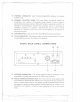
-..- -,...-..--- r POWER CORD CONNECTION: POSITIVE GROUND SYSTEM If you are operating on a positive ground system, connect the black DC power cord from the transceiver to the negative, or (-), battery terminal or other convenient point, and connect the red power lead to the chassis or vehicle frame, or (+) battery terminal.
... ===-- --= - OPERATING PROCEDURE TO RECEIVE: The G RANT operates on 40 AM channels, 40 Upper Side Band channels and 40 Lower Side Band channels. When you receive the SSB signal in the proper mode (USB or LSB), audio sound may be either too high pitched or Iow pitched, indicating that your receiver may not be tuned to the exact same frequency as the transmitter to which it is listening. The G RANT is equipped with a Clarifier.
". "'-' . ~- - - = I CONTROLS AND THEIR @ VOLUME @ (J) SQUELCH FUNCTIONS @ @ - MODNB/ANL BRITE o"Q) CD @ CH9 - 0 F . @ GRANT @ CID @ @ @ @ (jJ) @ 1. OFF/ON VOLUME: To turn the transceiver on, rotate this control clockwise past click. To turn the transceiver off, rotate the control counterclockwise click. Rotate the control clockwise for a comfortable audio level. past 2.
- - --- - 5. MIC GAIN: This control is used to adjust, as required, microphone input sensitivity for optimum amount of modulation in transmit. UNIDEN CORPORATION OF AMERICA citizen's band transceivers have been designed to permit the user to attain levels of modulation up to 100% depending on the setting of the microphone gain control, using the microphone provided with the unit. UNIDEN's automatic compression and peak limiting circuits assure maximum modulation with minimum distortion. 6.
-- 13. CHANNEL INDICATOR: number in use. ----.--. Light Emitting Diode(LED) indicates the channel 14. CHANNEL SELECTOR KNOB: This knob selects the desired channel for transmission and reception. All channels, except channel 9, may be used for communications between stations. Channel 9 has been reserved by the F.C.C. for emergency communications involving the immediate safety of individuals or immediate protection of property. Channel 9 also may be used to render assistance to a motorist. This is an F.C.
- -==== <--=====0 --- 1= 19. EXTERNAL SPEAKER JACK: The External Speaker Jack is used for remote receiver monitoring. The external speaker should have 8 ohm impedance and be rated to handle at least 4.0 watts. When the external speaker is plugged in, the internal speaker is automatically disconnected. 20. POWER JACK: This jack permits connection of the D.C. power to the transceiver. A power cord is supplied with the radio.
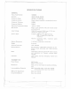
- =-- ---= r SPECIFICATIONS GENERAL F.C.C. Type Number Channels Frequency Range Frequency Control 1005002 40AM, 40LSB, 40USB 26.965 to 27.405 MHz Frequency Tolerance Phase Locked Loop(PLL) synthesized circuitry. 0.005% Frequency Stability 0.001% Operating Temperature Range Microphone -20°C to +50°C Plug-in type; dynamic with push-to-talk switch and coiled cord. Input Voltage 13.8V DC nominal, 15.9V max., 11.7V min. (positive or negative ground). Current Drain Transmit: AM full mod., 3A maximum.
<:::::C Frequency Response AM and SSB: 350 to 2500 Hz. Output Impedance SSB Filter 52 ohms, unbalanced. 7.8 MHz, crystal lattice type 6 dB @2.2 kHz 60 dB @4.6 kHz RECEIVER Sensitivity SSB: Less than 0.25 pV for 10 dB (S+N)/N at greater than Y2watt of radio output. AM: Less than 0.5 pV for 10 dB. (S+N)/N at greater than % watt of audio output. Selectivity Cross Modulation Image Rejection SSB 6 dB @2.2 kHz, AM 6 dB @7.5 kHz. More than 55 dB. More than 60 dB. I.F.
r~ SERVICING YOUR TRANSCEIVER The technical information, diagrams and charts will be supplied upon request. It is the user's responsibility to see that this radio is operating at all times in accordance with the F.C.C. Citizens Radio Service regulations. We highly recommend that you consult a qualified radiotelephone technician for the servicing and alignment of this CB radio product. Please refer to the WARNING information contained in the 1st page of this Owner's Manual.
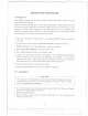
.---r OPERATOR TROUBLESHOOTING Should be unit malfunction or not perform properly, the operator should perform the procedures il.dicated below: 1. If the transceiver is completely inoperative. * Check the power cord and fuse. 2. If trouble is experienced with receiving. * Check ON/OFF VOLUMECONTROLsetting. * Be sure SQUELCH is adjusted properly. Is the radio over-squelched? * Check to see that the radio is switched to an operational mode. 3. If trouble is experienced with transmitting.
-==::: r=- NOTES -13 I - -- -.
'--'== - r NOTES I . .
CIRCUIT DIAGR~M FOR GRANT [I r.c.- ""., I TR' ZSCI615L ! L~ !.. ' ~--------------------------------------------------------------------------TRZZ$CI615LTR! ZSCI13OL 1ROZSC94- TR5ZSC94- TR6ZSC90SAQ TRT2SA"3PTReZSC94SAO TR9ZSCl615L FET1 !S"SB TRIO ZSC.OSAO ,,- I = l_-;__-;;;..; ~ ~' . , ..~ ~~~fi] t:-"lil F I~ I :1 1 I I L ~J~ I . ,'.' , :, -a . :, I I ~ ,. ""'TAo<' A",.,,"'",.O- "LUES U""" OTH""'" NOTEO "'",,0 OH.. .' .,. OH. 1 RE""OR .ATT..ES A" ",. UN"" OTH""'" 'P"""O. A.
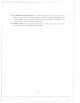
BLOCK DIAGRAM FOR GRANT r ~ I I I , I I I I z '" ~ DIMMER ~-t: I ~:i u I I -- I I I ..J ANT I I I I I I I I I I I I I I I ,-+ r-- --1 ~--I' i I L_d'-°~ n - + - -t I g ~ ~ t:. u; - I I J - I,I! -+-_.J ---~ I : ~ I 5; ... )( ..., 1 - DC 13.8V ,.
- ---=== r~ I ~ uniden TWO-YEAR WARRANTOR. UNIDEN CORPORATION LIMITED WARRANTY OF AMERICA ("UNIDEN") ELEMENTS OF WARRANTY. UNIDEN warrants, for the duration of this warranty, its UNIDEN CB Product to be free from defects in materials and craftsmanship with only the limitation or exclusions set out below. WARRANTY DURATION.