" H ~--- .
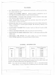
-_. = ( ==-- '-- c= RADIO BACK PANEL VIEW EXTERNAL SPEAKER Jack PA SPEAKER Jack POWER Cord Jack (f) @ MODEL NO.: MC-4700 DOe 10: SANTAONIC AGENCIES MADE IN TAIWAN SERIAL NO. (f) - POWER + PTY,LTD. SERIAL NUMBER AltT (1) ANTENNA Connector IMPORT ANT! This above pictorialdisplay shows the location of the various accessory, antenna, and powerreceptacles,as well asthe SERIAL NUMBER.
-=== -- SPECIFICATIONS f' GENERAL Channels Frequency Range Frequency Control Frequency Tolerance Frequency Stability Operating Temperature Range Microphone 10 AM, 10 USB 27.680 to 27.980 MHz Phase Locked Loop(PLL) synthesized circuitry :1:0.005% 0.001 % -20°C to +50°C Plug-in type, dynamic with push-to-talk switch and coiled cord Input Voltage 13.8V DC nominal, 15.9V max., 11.7V min. (positive or negative ground). Transmit: AM full mod., 2.2A; SSB 12 watts PEP output, 2A.
- RECEIVER Sensitivity Selectivity Cross Modulation Image Rejection I.F. Frequency AM and SSB RF Gain Control Automatic Gain Control Squelch Noise Blanker Clarifier Range Audio Output Power Frequency Response Distortion Built-in Speaker External Speaker (Not Supplied) - --_.- SSB: Better than .251J.Vfor 10dB (S+N)/N at greater than % watt of audio output AM: Better than .51J.Vfor 10 dB (S+N)/N at greater than % watt of audio output SSB and AM: 6 dB @ 4.2 kHz, 60 dB @ 7.
-====: i <:::::: . . . . . . . .. . FEATURES ALL SOLID STATE: IC and Transistorized construction, with Iow current drain, for a long, trouble-free life. LARGE LED CHANNEL DISPLAY: Channel number is displayed by use of LED (light emitting diode) display for ease of channel selection. CLEAN SIGNAL: Transmitter audio processing circuitry produces a clean signal with maximum legal modulation, for best range.
- Loop(PLL) techniques to provide crystal controlled ... - .--- transmit and receive operation on all 10 channels. The PLL circuitry assures ultraprecise frequency control. It is designed to meet the Department of Communications requirements applicable to equipment operating in the Inshore Boating Radio Communication Service, and is not to be used for any other purpose, RB244 of the D.O.C.
' Ii -. ~._7- NOTE: See ground connection under GENERAL INFORMATION for more de- i tail. 4. Connect the black wire to ground. Consult a marine electrician if in doubt. Any convenient location with good electrical contact may be used. (remove paint). 5. Mount the microphone hanger on the side of the unit or near the unit, using two screws supplied. When mounting in a boat, place the hanger on the dash so the microphone is easily accessible.
- r~ - ----- - , I used has been specifically designed for marine applications. Before installing the transceiver in a boat, consult your dealer for information regarding an adequate grounding system and prevention of electrolysis between fittings in the hull and water. i AC OPERATION To operate the transceiver from AC current as the power source, you will require a separate power supply capable of supplying 2.5 amps at a 13.8V DC output with a nominal input voltage of 240 volts AC, 50/60 Hz.
"- -'-. --~"""','~m r II i MIC/RF GAIN CONTROL CLARIFIER DIGITAL LED CH88 INDICATOR CHANNEL INDICATOR TX/RX RF POWER/liS" METER TWO COLOR I I INDICATOR . CH'BB SIGNAL,jPOWER CHArjNEL .
.-----.---. 5. CLARIFIER: The clarifier is normally set to the center position. This has several uses and can greatly enhance receiver operation. If a receive slightly off frequency, th is control can be operated to optimize the signal. This control is primarily intended to tune in SSB signals, but, it also used to optimize the AM signal. 6. MIKE GAIN: This control is used to adjust, sensitivity for optimum amount of modulation feature signal is receive may be as required, microphone input in transmit.
r I I 2. I \ TX/RX INDICATOR: The TX/RX light in the upper right corner of the front panel lights in red color when the microphone button is pressed and transmitter is in operation. It lights in green color when the microphone button is released and the receiver is in operation. PUSH-TO-TALK MICROPHONE I \ The receiver and transmitter are controlled by the push-to-talk switch on the microphone. Press the switch and the transmitter is activated. Release the switch to receive.
-~-_. ~ ,~ ~. ~ uniden@ 12 MONTHS FULL WARRANTY WARRANTOR. SANTRONIC AGENCIES PTY. LTD. 13 Garema Circuit, KingsgroveNSW2208 ("SANTRONIC"). ELEMENTS OF WARRANTY. SANTRONIC warrants, for the duration of this warranty, its UNIDEN Marine Product to be free from defects in materials and craftsmanship with only the limitation or exclusions set out below. WARRANTY DURATION.