UBCT9 Scanner 250 Channels 12 Bands Programmable Trunk Tracker lll with Close Call RF Capture UBCT9 OM 1 12/11/07 3:52:21 PM
Precautions Before you use this scanner, please observe the following: WARNING! Uniden does not represent this unit to be waterproof. To reduce the risk of fire, electrical shock, or damage to the unit, do not expose this unit to rain or moisture. IMPORTANT! • Changes or modifications to this product not expressly approved by Uniden, or operation of this product in any way other than as detailed by this Operating Guide, could void your authority to operate this product.
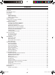
Contents Introduction.............................................................................................................................................1 Front and Rear Views.............................................................................................................................2 Icon Display............................................................................................................................................3 Terminology....................................
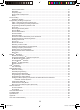
Search Hold Feature......................................................................................................................27 Data Skip........................................................................................................................................27 Frequency Skip..............................................................................................................................27 Storing Search Frequencies.......................................................
Introduction The UBCT9 is a state-of-the-art Trunk Tracking Scanner with Bear Tracker technology. It can store 250 frequencies such as police, fire/emergency, marine, railroad, air, amateur, and other communications into 5 banks of 50 channels for a total of 250 channels.
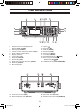
Front and Rear Views UBCT9 1. Squelch Control / Flash Brightness Selector (SQL, FLASH) 2. Alerting Light (ALERT) 3. Volume Control / Alert Tone Selector (VOL) 4. Close Call RF Capture (C.C.) 5. Display (window) 6. Lockout Key (L/O) 7. Delay Key (DELAY) 8. Service Key (SVC) 9. State Scan or Private Scan Key (SCAN) 10. State Key (STATE) 11. Numeric Keypad 12. 13. 14. 15. 16. 17. 18. 19.
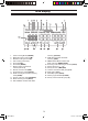
Icon Display 1. 2. 3. 4. 5. 6. 7. 8. 9. 10. 11. 12. 13. Trunk Tracking Mode (TRUNK) Motorola trunking channel (M) EDACS trunking channel (E) LTR trunking channel (L) Scan list (LIST) Scan bank (BANK) Bank’s number and ID’s list number (1 2 3 4 5) Remote control mode (RMT) Programming is locked (PROG) State scanning and Private scanning mode (SCAN) Service scanning mode (SERVICE) Band searching mode (SRCH) POLICE Bank included with State scanning (POLICE) 14.
Terminology What is Scanning? Unlike standard AM or FM radio stations, most two-way communications do not transmit continuously. The UBCT9 scans the Frequencies you have programmed into the Scanner’s channels until it finds an active frequency. Scanning stops on an active frequency and remains on that channel as long as the transmission continues. When the transmission ends, the scanning cycle resumes until another transmission is received.
Sharing of the available public service frequencies, or trunking, allows cities, counties, or other agencies to accommodate hundreds of users with relatively few frequencies. Following a conversation on a trunked system using a scanner is difficult, if not impossible. Because when there’s a short break during the conversation you’re monitoring, it’s possible that the talk group will be assigned to a completely different frequency in the trunked system. This type of scanning is difficult and frustrating.
Feature Highlights • Pre-programmed frequencies specific to each • Pre-programmed Trunked frequencies • Close Cal ™ RF Capture Technology You can set the scanner so it detects and provides information about nearby radio transmissions. • Pre-programmed Service Scanning by the following service banks; - Police - Rail Roads - Aircraft (except Aeronautic radio Navigation (108-117.
Included with Your Scanner Package • UBCT9 Scanner • AC Adapter • DC Power Cord • Cigarette Lighter Adapter Plug • Telescopic Antenna • Window Mount Antenna • Operating Guide • UBCT9 SS Programming Software CD • Australian Scanner Frequencies CD • Other Printed Materials • Mobile Mounting Bracket If any of these items are missing or damaged, immediately contact your place of purchase.
Installing the UBCT9 For Home Use (Desktop Installation) 1. Insert the DC plug end of the AC Adapter into the DC 12V jack on the rear panel. 2. Plug the AC Adapter into a standard 240V AC wall outlet. 3. Plug the Telescoping Antenna into the ANT connector. Extend the antenna to its full height. For frequencies higher than 406 MHz, shortening the antenna may improve the reception. 4. Use the desktop stand for a better viewing and operating angle.
3. Drill the necessary holes and secure the mounting bracket in place using the screws provided. 4. Mount the radio to the bracket only after the wiring has been connected to the rear panel. Connecting the Power Cord Note: If you are not experienced in connecting accessories to the vehicle fuse box, please see your automotive dealer for advice on proper installation. Installation for everyday use: 1.
Typical Mounting Methods The UBCT9 can be conveniently mounted on a table, bulkhead, overhead, or any other desired location with the supplied mounting bracket (refer to figure below for typical mounting methods). Caution: Make sure there are no hidden electrical wires or other items behind the desired location before proceeding. Check that free access for mounting and cabling is available.
Applying Power for Vehicle Installation You can power your scanner using the supplied DC cigarette lighter power cord or an DC power cord. DC power Installation To power the scanner from a vehicle’s 12V power source (such as a cigarette-lighter socket), you need a cigarette-lighter adapter. To connect an DC cigarette-lighter power cable, insert its barrel plug into the DC 12V jack on the rear of the scanner, then plug the power cable into your vehicle’s cigarette lighter socket.
Applying Power Using Standard AC Power To power the scanner from an AC outlet, use the provided AC adapter with a 5.5 mm outer diameter/2.1mm inner diameter tip. Caution: You must use a Class 2 power source that supplies 12V DC and delivers at least 500 mA. The cord connector’s center tip must be set to positive and its plug must fit the scanner’s DC 12V jack. Using an adapter that does not meet these specifications could damage the scanner or the adapter.
Scanning Overview You can scan in one of five ways: 1. Close Call RF Capture When you activate Close Call your scanner will detect nearby strong radio frequencies. You may run Close Call in the background of any of the four options below or on its own. 2. Service Scanning Press SVC to select one of the six services to find an active frequency. Police, Railroad and AM CB service frequencies are valid for Australia only.
How Squelch Works Think of “SQUELCH” as a gate. If the gate is too low (squelch too low), everything (all noise as well as signals) gets through. If the gate is set too high (squelch too high), nothing gets through. If the gate is set just right (squelch set properly), just the desired signals get through. Setting the Squelch 1. To set the squelch, press HOLD/RESUME to stop scanning. 467.8500 2. Turn SQL fully counterclockwise until hiss heard.
State Scanning Press POLICE, FIRE or AMBULANCE and the scanner scans through police, fire or Ambulance Frequencies and “SCAN” scrolls from right to left in the display. When in the State Scan mode, press STATE and the menu of states will appear. Press POLICE. The scanner will scan through Factory Programmed Police Frequencies and ”POLICE” appears in the display. Press FIRE. The scanner will scan through Factory Programmed Fire Frequencies and ”FIRE” appears in the display. Press AMBULANCE.
5. To scroll repeatedly, press and hold or and STATE. After 3 seconds, the scanner will begin to scan through the Police frequencies (Police only). 6. If you want to start scanning immediately, press HOLD/RESUME. State Scan Hold 1. When scanning stops on a desired frequency, press HOLD/RESUME to hold at that frequency as long as you like. While ”HOLD” appears in this mode, you can use or to move up or down the frequency steps. During Hold mode, you can see all frequencies sequentially.
Close Call RF Capture ™ Your scanner’s Close Call feature lets you set the scanner so it detects then displays the frequency of a nearby strong radio transmission. Close Call RF capture works great for finding frequencies at venues such as malls and sporting events. You can set the scanner so Close Call detection works “in the background” while you are scanning other frequencies, turn off normal scanning while Close Call is working, or turn off the Close Call feature and use the scanner normally.
When the scanner is staying on a frequency, “- - - - - -“ will be displayed during “C-C” term instead of the frequency. Close Call Operation 1. When a signal is detected, the scanner alerts (depending on the Set Close Call Alert setting, page 20) and immediately jumps to the Close Call frequency. But, the frequency is not displayed. NOTE: Close Call does not work during selecting the band search, selecting the State code and programming mode. If you want to confirm the frequency, press any key.
5. If you press DELAY, you can set DELAY function. ‘DLY’ appears on the screen. 6. If you press DATA, you can set DATA Skip function. ‘DATA’ appears on the screen. Set Close Call Option 1. Press and hold C.C for 2 seconds to display the Close Call option menu. “C-C.bnd” : Selecting Close Call Bands. “C-C.ALt” : Close Call alert option. “C-C.PS” : Setting of pager screen 2. Press or , to select the menu, and then press E.
Set Close Call Alert This option controls whether the scanner sounds an additional alert tone when a Close Call signal is detected. Press or to select the option, and then press E. Setting of pager screen This option sets whether the scanner screens common pager frequencies from hits during Close Call searching. 1. Press or to select the option, and then press E. Pager Screen On : The scanner ignores hits on common pager frequencies.
Private Bank Scanning Programming Frequencies into Channels Before the scanner begins Private Bank scanning, you must program a frequency into at least one channel. Visit our website (www.uniden.com.au, www.uniden.co.nz) for information on known frequencies. Frequencies for Australia can be found on the Australia Scanner Frequencies CD included with the UBCT9. You will need to program each frequency into the scanner’s channels in order to hear these frequencies. 1.
Duplicate Frequency Alert If you enter a frequency which has been stored in another channel, you will hear an error tone and the other channel displays. SCAN Press (decimal key) to clear and start again. ––– OR ––– Note: Press E again to store the frequency in both channels. The smallest channel appears on the display when you store same frequency in two or more channels. Memory Lock To avoid the accidental programming frequencies and talk group IDs, you can lock the memory with Memory Lock.
Hold/Resume If you want to stop on a channel during scanning, press HOLD/RESUME. If you want to resume scanning, press HOLD/RESUME. Direct channel access: There are several ways to access a specific channel quickly. 1. Press HOLD/RESUME. 2. Using the keypad, enter the channel number. 3. Press HOLD/RESUME again. SCAN SCAN SCAN Note: You can also use the SCAN, pressing HOLD/RESUME. or key instead of Channel Lockout You can lockout any channel so it is not checked during normal scanning.
Restoring All Locked-out Channels You can restore all locked-out channels in a bank only when a bank is selected for scan. If you have deselected a bank and you want to restore all of its locked-out channels using the steps below, you must press SCAN until “SCAN ” appears and then enter the number of the bank on your keypad. 1. Press HOLD/RESUME. Note: You must be in Hold mode before restoring all locked-out channels. 2. Press and hold L/O for about 2 seconds.
Service Scanning The service scan feature allows you to rotate through the following six service banks. (1) Police* (2) Rail Roads* (3) Aircraft** (4) Marine Band (5) UHF CB Band (6) AM CB BAND* * Preset frequencies valid for Australia Only (not valid for NZ) ** Except Aeronautical Radio Navigation (108-117.9875 MHz) 1. Press SVC to select a Service. ‘SERVICE ‘ appears on the display with the current service bank below. 2. Continue pressing SVC until your desired Service is displayed.
Band Search Setting a Search Band The UBCT9 can search up to 12 separate frequency ranges to help you discover new stations in your area. To set a Search Bands, enter into the Band Search mode. Band No Range (Mhz) Mode Step Display 1 0025.0000 - 0027.9950 AM 5kHz 25 - 28 2 0028.0000 - 0069.9900 FM 10kHz 28 - 70 3 0070.0000 - 0087.9875 FM 12.5kHz 70 - 88 4 0088.0000 - 0107.9000 WFM 100kHz 88 - 108 5 0108.0000 - 0136.9875 AM 12.5kHz 108 - 137 6 0137.0000 - 0147.
• While Trunking is operating in scan mode, press SRCH and it will move to ID Search mode and ID Scan mode. Search Hold Feature 1. Press HOLD/RESUME at anytime to stop the search. To move up or down 1 frequency key. step, use the or 2. Press HOLD/RESUME to resume searching. Data Skip A scanner will normally stop on any transmission it receives. This means the UBCT9 will occasionally stop on data signals and unmodulated transmissions.
Storing Search Frequencies You can quickly store any frequency you find during Search. 1. During Search, press HOLD/RESUME. If you want to change the frequency, use the or key to move up or down 1 frequency step. Then press E. Or when the scanner stops on the frequency you want to store, press E. 2. Select a bank you want to store by using the keypad. The smallest empty channel number and the frequency alternately appear on the display.
Trunk Tracking Your UBCT9 is tracks three major types of trunked radio systems. These systems are described here. • MOTOROLA - Including Type I, Type II, Hybrid, SMARTNET, and Privacy Plus. Motorola systems are widely used by public safety and business users. Most are on the 800 MHz band, and recent systems are appearing on other bands. (see page 43). • EDACS - Including “Wideband” 9600 baud and SCAT.
Programming Trunking Frequencies There are three steps for programming a trunked system: 1. Program the Trunk Type – What type of system will the scanner be tracking, Motorola Type II, Type I, EDACS, LTR, etc. 2. Program the Trunked Frequencies – Within a trunked system, the frequencies are shared among all the users, called “Talk Groups”. 3. Program the Talk Groups – Within the trunked system, each agency or department is assigned a Talk Group ID.
*** Requires programming of frequencies in exact order and location. STEP 2: Programming Trunking Frequencies 1. Select and press E. Use the numeric keypad and a frequency for the trunked system. For example, enter . (decimal key) to enter Note: To clear a mistake while entering a frequency, press (decimal key) twice, and start over. 2. Then press E. The “E” (EDACS), “M” (Motorola) or “L” (LTR) appears depending on the trunked system selected.
In order to program Talk Group ID’s, you must first complete Step1–“Selecting Trunking System Type”, page 30 and Step 2 – “Programming Trunking Frequencies”, page 31. 1. After programming a frequency, press HOLD/RESUME to return to the main screen of system type selected and select . Then press E. 2. Select the Scan List location by using the or key. 3. Enter the Talk Group IDs for each trunk system as follows. To enter a Type 2 Talk Group ID: 1. Enter the ID you want to store by using the keypad. 2.
Please see page 42 for more information. 1. Enter the Area Code. 2. Enter the Home Repeater number. 3. Enter the ID you want to store. 4. Press E. Note: To clear a stored ID while entering an ID, press 0 and E successively, and start over. Receiving Trunked Systems When you have properly programmed all the frequencies for a trunked system, you can monitor the system in several different ways. You will find that Search, Hold, Lockout, Scan and Delay are all similar to conventional scanning.
Note: One Scan List must always be active. If you try and deactivate all the Scan Lists, Scan List 1 will automatically be active. 3. To restore a Scan List to active scanning, press its number again. F Remember! When you press TRUNK in the Trunking mode, you can be out of the Trunking mode and enter into Private Scan Hold mode. Note: appears on the display during Trunk Scan instead of simply . ID Scan Hold Feature If you want to stop on a ID during ID scanning, press HOLD/RESUME.
ID Monitor Mode By using ID Monitor mode, you can determine which talk groups are the most active without hearing conversations. 1. Press and hold SRCH for 2 seconds until you hear two beeps. Then begins flashing and all active talk group IDs appear on the display every 0.5 seconds. 2. To activate ID search mode, press SRCH. Note: Lockout ID also appears on the display.
ID Lockout Like conventional scanning, it’s possible to lockout unwanted traffic. This is particularly important in trunked systems because in many areas, water meters, door alarms, traffic signals, and other mechanical devices are assigned IDs just like other users. Also some departments scramble or encrust their communications, and you may want to lock out these unintelligible broadcasts. To Lockout an ID, press L/O on the ID you want to lockout. The ID is locked out. You can Lockout up to 100 IDs.
Setting the Delay Mode for Trunking Mode A default delay of 2 seconds is automatically set for each talkgroup for ID Scan mode and ID Search mode. To set the delay feature on or off, press DELAY while trunking, “DLY” will appear or disappear depending on your setting. Trunking Frequency Confirmation You can check the frequency while a talkgroup ID is active. Press the key ,and the active frequency on which the talk group is transmitting will flash on the display.
Multi-Track The UBCT9 allows you to track more than one system at a time. Here are some highlights of this feature: • • • You can actually track up to 5 trunking systems at one time. You can trunk scan, or search and scan conventional frequencies at the same time. You can program conventional frequencies in the same bank as trunking systems.
EDACS® Reception EDACS Tracking ® TrunkTracker III now allows tracking of EDACS® trunked systems. Until now these widely used systems have been almost impossible to monitor with a conventional scanner. With your TrunkTracker III listening to EDACS(s) is remarkably easy, and perhaps even easier than conventional scanning. EDACS systems use ‘Transmission Trunking’, which means that each transmission is assigned a new frequency.
An EDACS® Trunked system This chart shows how talkgroups are organized within an EDACS system at the Agency level. The individual talkgroups cannot be shown at this scale because there are over 2000. However the chart can show the 16 Agencies in this example. The system is logical and easy to understand. EDACS systems are typically arranged in an outline structure. The system users are given blocks of talkgroups. Sizes vary but most large cities and other agencies have blocks of 128 channels.
Special EDACS ® Features AFS Partial Entry Feature AFS is Uniden’s method of encoding EDACS talkgroups. AFS stands for ‘Agency-Fleet-Subfleet’. AFS talkgroups are used in all EDACS reception -- in ID Search, ID Lockout and ID Scan. The powerful AFS Partial Entry feature designed into the UBCT9 lets you use either a complete talkgroup code, or just the most significant part. This feature lets you expand or narrow searching and scanning to one of 4 levels.
LTR ® Reception LTR ® Tracking LTR ® (Logic Trunked Radio) systems are trunking systems used primarily by business or private communications service providers, such as taxicabs, delivery trucks, and repair services. These systems encode all trunking information as digital subaudible data that accompanies each transmission. Users on an LTR system are assigned to specific talkgroups, which are identified by the radio as six digit numbers.
Motorola Reception Motorola Tracking There are really two types of Motorola trunking systems. These are usually referred to as Type I and Type II systems. Type I only occurs on some 800 MHz systems. All VHF and UHF trunking systems use Type II. One important distinction between these two systems is the amount of data transmitted by each radio when its push-to-talk button (PTT) is pressed. Every radio in a trunked system is assigned a unique ID so the central site computer can identify it when it’s used.
Fleet Map Programming If you have programmed a trunk tracking bank for Motorola, press TRUNK to start MultiTrack, and you will see user IDs on the display. Since the UBCT9 defaults to Type II systems, all the IDs will appear as numbers. However, if you notice a mix of odd and even user IDs, for example 6477, 2560, 6481, 6144, 1167, etc., then you are probably monitoring either a Type I or Hybrid systems. You may also notice that you are missing responses when you hold on an active ID.
The next available block appears on the display. 6. Repeat step 5 until you have selected a size code for each block. For details about each size code, see “Fleet Map Size Codes” in the Appendix. Programming a Hybrid System A Hybrid system is simply a Type I system with some blocks designated as Type II blocks. To program a Hybrid system, follow the steps listed in “Programming a User Fleet Map” in the previous section. However, if you want a block to be Type II, select Size Code .
9. Use the keypad to enter a new Offset Channel, then press E. Note: • • • You can only input within a range of 380-759. If the system is not tracking properly, you may need to try a new Base Frequency or Offset Channel, or you may be missing frequencies from the system. You can set up to three Base, Spacing and Offsets for Motorola VHF/UHF trunked systems.
Read the descriptions of the Plan 1~2 for details on which may apply for you. PL1(plan1): If the last three digits of ALL the frequencies in use end in one of the following three digits (125, 375, 625, or 875), use PL1(plan1). PL2 (plan 2): If the last three digits of ALL the frequencies in use end in one of the following three digits (000, 250, 500, or 750) use Plan 2. Of course, you will know the Control Channel frequency itself so that will help you determine the proper plan.
Remote Interface You can communicate and program your UBCT9 in numerous ways with peripheral devices using a Remote Interface Cable port. This radio offers the following modes: • PC Control mode Program and control your scanner from a PC using Uniden’s UBCT9 Scanner Software. • Clone mode Clone all the frequencies, trunking talkgroups, and fleet maps programmed into your scanner to another UBCT9 scanner.
Start Remote Mode and Change Transfer Speed: 1. Press and hold RMT for 2 seconds to activate the Remote mode. 2. Select the transfer speed except for the scanner will start Remote mode. , then press E and A unique feature of the UBCT9 is that all the front panel keys on the radio remain operational in Remote mode.
To connect the Scanner to Scanner: Plug the male end of the RS232C straight interface cable into the remote port on the rear of one of the two scanners. Then connect the DB-9 to DB-9 null modem adapter to the cable. Plug the other end of the null modem adapter into the other scanner (DB9 Gender Changers are also available at your local electronics store.). You can clone all of the programming of one UBCT9 into another, including frequencies, talkgroup IDs, delay settings, etc.
5. The data transfer begins from the First Unit to the Clone Unit. During the data transfer, both scanners show the following displays. When the data transfer is complete, displays. If the data transfer is not successful, the following error message will appear. Note: • To clear , press (decimal key). • Once you have completed the cloning of the scanners, reset the scanners by turning the scanners OFF and then ON again.
Care and Maintenance General Use • Turn the scanner OFF before disconnecting the power. • Always write down the programmed frequencies in the event of memory loss. • If memory is lost, simply reprogram each channel. The display shows 000.0000 in all channels when there has been a memory loss. Location • Do not use the scanner in high-moisture environments such as the kitchen or bathroom. • Avoid placing the unit in direct sunlight or near heating elements or vents.
Troubleshooting If your UBCT9 is not performing properly, try the following steps. Problem Suggestion Scanner won’t work. 1. Check the connections at both ends of the AC Adapter. 2. Turn ON the wall switch of your room. You could be using an outlet controlled by the wall switch. 3. Move the AC Adapter to another wall outlet. Improper reception. 1. Check the antenna connection. 2. Move the scanner. 3. You may be in a remote area which could require an optional multi-band antenna.
If you experience difficulty while in TrunkTracker mode, try the following steps. Problem Suggestion Scanner won’t track. 1. Missing the Data Frequency. 2. Change to a Type 1 Scanner setup. Review Fleet Map Programming on page 44. Scanner won’t stop during Scan List mode. 1. No IDs have been programmed. 2. The IDs you have stored are not active. Scanner will not acquire data channel. 1. Adjust the squelch for Trunking mode - refer to page 29. 2. Missing the frequency used for the data channel.
Specifications Certified in accordance with FCC Rules and Regulations Part 15, Subpart C, as of date of manufacture. Channel: 250 Banks: 5 (50 channels each) Service Bands: 6 preprogrammed search bands Frequency Range: 25.0-28.0 MHz 28.0-70.0 MHz 70.0-88.0 MHz 88.0-108.0 MHz 108.0-137.0 MHz 137.0-148.0 MHz 148.0-174.0 MHz 174.0-225.0 MHz 225.0-400.0 MHz 400.0-512.0 MHz 806.0-956.0 MHz 1240.0-1300.
Appendix State Code Order No. Code State Name 1. ACT Australian Central Territories 2. NSW New South Wales 3. NT Northern Territory 4. NZ New Zealand 5. QLD Queensland 6. SA South Australia 7. TAS Tasmania 8. VIC Victoria 9.
Preset Fleet Maps E1P2 57 UBCT9 OM 57 12/11/07 3:54:06 PM
58 UBCT9 OM 58 12/11/07 3:54:07 PM
User Defined Fleet Maps Type I Programming Information When a Type I system is designed, the address information for all the IDs are divided into 8 equal sized blocks. When you program your scanner to track a Type I system, you must select a size code for each of these blocks. When you have assigned a size code to all 8 blocks, you have defined the Fleet Map for the system you’re tracking. Each size code determines the number of Fleets, Subfleets, and IDs each block will have.
Fleet Map Size Codes Size Code Restrictions If you select SIZE CODE 12, 13, or 14, there are some restrictions as to which blocks can be used for these codes. • SIZE CODE 12 can only be assigned to Blocks 0, 2, 4, or 6. • SIZE CODE 13 can only be assigned to Blocks 0 and 4. • SIZE CODE 14 can only be assigned to Block 0. Since these SIZE CODES require multiple blocks, you will be prompted for the next available block when programming a Fleet Map.
MEMO 61 UBCT9 OM 61 12/11/07 3:54:09 PM
MEMO 62 UBCT9 OM 62 12/11/07 3:54:09 PM
One Year Limited Warranty UNIDEN UBCT9 Scanning Receiver IMPORTANT: Evidence of the original purchase is required for warranty service. WARRANTOR: Uniden New Zealand Limited. Uniden Australia Pty Ltd. ABN 58 001 865 498 Warranty only available in original country of purchase.
THANK YOU FOR BUYING A UNIDEN PRODUCT ©2007. Uniden Australia Pty Limited/Uniden New Zealand Limited Printed in China.