UH8010NB Mini Compact UHF CB Transceiver For more exciting new products please visit our website: Australia: www.uniden.com.au New Zealand: www.uniden.co.
Contents Introduction Controls & Connectors Indicators Included with your UH8010NB Transceiver Connecting the Microphone Mounting the MIC Hanger Operation Turning on the Power Setting the Squelch Level Monitor Selecting a Channel Programming the Instant Priority Channel Recalling the Instant Channel Transmitting Call Function Using Repeater Channels Operating the UHF CB Radio in Duplex Mode Scanning Open Scan (OS) Mode Group Scan (GS) Mode & Priority Watch Add/Remove Channels from SCAN Memory CTCSS & DCS Bu
Introduction The Uniden UH8010NB is designed to provide you with years of trouble free service. Its rugged components and materials are capable of withstanding harsh environments. Please read this Operating Manual carefully to ensure you gain the optimum performance of the unit.
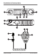
Controls & Connectors 1 6 2 5 7 4 3 8 9 10 15 11 13 12 14 16 UNIDEN UH8010NB 4 UHF CB Transceiver
Controls & Connectors 1 10 UHF Antenna Connection Menu Button / Monitor function (press & hold) 11 CALL - Call Tone Button 2 PUSH control - Squelch 12 INST - Instant Channel Select (press) /Power On/Off (press & hold) Button ROTARY control - CHANNEL Selector 3 4 / control 13 PTT - Push To Talk Button 14 MICROPHONE - Volume Up/Down 15 RJ45 type plug Channel Scan button / Scan Memory (press & hold) 16 Front MIC Jack Cover 5 Liquid Crystal Display (LCD) 6 MIC - Front Microphone Jack 7 Speake
Indicators 6 5 4 3 2 1 1 - Receive Signal Level (Channel Busy Indicator) - Transmit Signal Power Level 2 - Channel Number / Menu Item Setting 3 - CTCSS/DCS Code number / Menu Item 4 - Scan mode 5 - Channel in Memory 6 - Instant Channel UNIDEN UH8010NB 6 UHF CB Transceiver
Included with your UH8010NB Transceiver Bt Nac 80ra10 UHUlt Comp Radio UHF For more Heavy Duty Microphone e Mobil our e visit ucts pleas m.au new prod .uniden.co .nz exciting ralia: www .uniden.
Connecting the Microphone MIC Jack Push the MIC plug at the end of the microphone into the MIC jack until the connection locks into place. Gently tug the MIC cord to test that the connection is locked. Use the rubber cover which is on the MIC cord to seal the MIC jack entry from dust. Disconnecting the MIC from the MIC Jack Pull back the rubber cover and move it down along the cord.
Mounting the MIC Hanger The Microphone Hanger comes in two parts. How and where you mount the MIC hanger will determine which parts to use. Conventional Mounting with Screws Use the front part of the MIC Hanger only. Locate a suitable mounting position and mark and drill two 3mm holes. Fix the MIC Hanger into place with screws. Conventional Mounting with Double Sided Tape (not supplied) High quality Double-Sided tape can be found at good retail stores.
Operation Turning on the Power Press and hold the Power/Channel Selector. Low-Voltage/High-Voltage Alert If the power supply voltage exceeds 18VDC, an alert tone sounds and dc HI flashes for 5 seconds. The power source must not exceed 25VDC otherwise permanent damage may occur to your radio, which may not be covered by the manufacturer’s warranty. NOTE If the input voltage falls below 10VDC, dc Lo flashes for 5 seconds. The power turns off automatically if voltage falls below 8.5VDC.
Operation oF(off) - squelch open. 1 - max sensitivity (min squelch) 5 - med sensitivity (med squelch) 9 - min sensitivity (max/tight squelch) NOTE You must select a channel which is not in use before setting the SQUELCH control. (see p.12 for “Selecting a Channel”). Think of the squelch control as a gate. If you increase the squelch level to maximum it raises the ‘Squelch gate’ so only the strongest signals get through.
Operation Monitor Press and hold to open the squelch and receive all weak signals. Press and hold again to cancel. Selecting a Channel Turn the Channel Selector to select the desired channel. NOTE For your reference a list of the available channels, corresponding frequencies and guidelines for their use and selection is printed on page 23. For Australia, Channels 05 UH7700 Seriesfor Standard Microphone and 35 areNB reserved Emergency Calls.
Operation Recalling the Instant Channel Momentarily press [INST] on the microphone at any time to return to the Instant Channel. Press [INST] again to return to the previous channel. Transmitting The UHF CB Radio uses UHF-CB Channels. NOTE For your reference a list of the available channels, corresponding frequencies and guidelines for their use and selection is printed on page 23. For Australia, Channels 05 and 35 are reserved for Emergency Calls. Select the desired channel.
Operation Standard Operation without the aid of a Repeater station. Operation with the aid of a Repeater Repeater Station (Duplex). The signal coming from your radio is received by the Repeater Station and the re-transmitted at the same time on another channel. This operation is called “Duplexing”. For example, CH01 on Duplex Mode will Receive on CH01 but Transmit on CH31 CH02 on Duplex Mode will Receive on CH02 but Transmit on CH32 etc...
Operation Operating the UHF CB Radio in Duplex Mode For this example we are adopting CH01 as the channel being used in your area for repeater use. 2 times. The duplex setting flashes. 1. Press / to change the setting 2. Turn the Channel Selector or press between simplex and duplex (“ r ” for repeater channels 01 - 08 or “ n “ for repeater channels 41 - 48). 3. Press to store the setting. to save & exit the menu mode. Only channels 4. Press and hold 01 - 08 and 41 - 48 are available for Duplex.
Operation 2. To deactivate SCAN, press . Open Scan (OS) Mode Allows continuous scanning of all selected channels. If an active channel is found, scanning will stop on that channel. If the received signal ceases, the unit will wait 3 seconds for the signal to return, otherwise scanning resumes. After transmission in scan mode, the unit will wait 20 seconds for the signal to return, otherwise scanning resumes. To skip the active channel, turn the Channel Selector.
Operation If the Priority Channel becomes active the radio will stay on that channel for as long as the signal is present. If the received signal ceases, Priority Scanning continues after 3 seconds. If scanning stops on a channel which is not a Priority Channel, the radio will continue monitoring the Priority Channel for activity while listening to the active one. To deactivate SCAN, press the button. Add/Remove Channels from SCAN Memory Select which Scanning Mode you wish to use; OS or GS.
Operation Busy Channel Lockout If the channel is already in use, you can prevent the UHF CB Radio from transmitting . This is particularly important when using CTCSS/DCS. 1. Press 4 times. The BCL setting flashes. 2. Turn the Channel Selector or press between ON or OFF. 3. Press / to change the setting to store the setting. 4. Press and hold to save & exit menu mode. Selecting the Call tone 1. Press 5 times. The call tone setting flashes. 2.
Operation Roger Beep 1. Press 6 times. The roger beep setting flashes. 2. Turn the Channel Selector or press between ON or OFF. 3. Press / to change the setting to store the setting. 4. Press and hold to save & exit menu mode. Beep On/Off 1. Press 7 times. The Beep setting flashes. 2. Turn the Channel Selector or press between ON or OFF. 3. Press / to change the setting to store the setting. 4. Press and hold to save & exit menu mode. Backlight Colours 1. Press 8 times.
Operation Backlight Brightness 1. Press 9 times. The Backlight Brightness setting flashes. 2. Turn the Channel Selector or press / between Off (oF), 1(Lo), 2(mid) and 3(Hi). 3. Press to change the setting to store the setting. 4. Press and hold to save & exit menu mode. LCD Flip 1. Press 10 times. The Flip setting flashes. 2. Turn the Channel Selector or press orientation. 3. Press / to change the flip to store the setting. 4. Press and hold UNIDEN UH8010NB to save & exit menu mode.
CTCSS codes table Code No. Frequency (Hz) Code No. Frequency (Hz) “oF’ OFF 20 131.8 1 67.0 21 136.5 2 71.9 22 141.3 3 74.4 23 146.2 4 77.0 24 151.4 5 79.7 25 156.7 6 82.5 26 162.2 7 85.4 27 167.9 8 88.5 28 173.8 9 91.5 29 179.9 10 94.8 30 186.2 11 97.4 31 192.8 12 100.0 32 203.5 13 103.5 33 210.7 14 107.2 34 218.1 15 110.9 35 225.7 16 114.8 36 223.6 17 118.8 37 241.8 18 123.0 38 250.3 19 127.
DCS codes table Code No. 1 2 3 4 5 6 7 8 9 10 11 12 13 14 15 16 17 18 19 20 21 22 23 24 25 26 27 28 29 30 31 32 33 34 35 DCS Code (Octal) 023 025 026 031 032 036 043 047 051 053 054 065 071 072 073 074 114 115 116 122 125 131 132 134 143 145 152 155 156 162 165 172 174 205 212 UNIDEN UH8010NB DCS Code (Octal) 223 225 226 243 244 245 246 251 252 255 261 263 265 266 271 274 306 311 315 325 331 332 343 346 351 356 364 365 371 411 412 413 423 431 432 Code No.
UHF CB Channel Guidelines NOTE Always listen on a channel (or observe the receive signal level meter) to ensure it is not already being used before transmitting. Channels 5 and 35 are used for emergency channels. CTCSS and DCS will not operate on these channels. Please follow these guidelines for channel use in Australia: • Channels 05 and 35 are Emergency Channels. • Channel 11 is a Calling Channel.
UHF CB Channels & Frequencies CH No. Simplex Mode Transmit / Receive Frequency (MHz) Duplex Mode Transmit Frequency (MHz) CH No. Simplex Mode Transmit / Receive Frequency (MHz) 1 476.425 477.175 (CH31) 21 476.925 2 476.450 477.200 (CH32) 22 476.950 (RX only) 3 476.475 477.225 (CH33) 23 476.975 (RX only) 4 476.500 477.250 (CH34) 24 477.000 5 476.525 477.275 (CH35) 25 477.025 6 476.550 477.300 (CH36) 26 477.050 7 476.575 477.325 (CH37) 27 477.075 8 476.600 477.
UHF CB Channels & Frequencies CH No. Simplex Mode Transmit / Receive Frequency (MHz) Duplex Mode Transmit Frequency (MHz) CH No. Simplex Mode Transmit / Receive Frequency (MHz) 41 476.4375 477.1875 (CH 71) 61 42 476.4625 477.2125 (CH 72) 62 43 476.4875 477.2375 (CH 73) 63 future use 476.9375 (RX only) future use 476.9625 (RX only) future use 476.9625 (RX only) 44 476.5125 477.2625 (CH 74) 64 477.0125 45 476.5375 477.2875 (CH 75) 65 477.0375 46 476.5625 477.
Warranty UNIDEN UH8010NB UHF CB Transceiver IMPORTANT: Satisfactory evidence of the original purchase is required for warranty service Please refer to our Uniden website for any details or warranty durations offered in addition to those contained below. Warrantor: The warrantor is either Uniden Australia Pty Limited ABN 58 001 865 498 (“Uniden Aust”) or Uniden New Zealand Limited (“Uniden NZ”) as the case may be.
Warranty Statement of Remedy: If the Product is found not to conform to this warranty as stated above, the Warrantor, at its discretion, will either repair the defect or replace the Product without any charge for parts or service. This warranty does not include any reimbursement or payment of any consequential damages claimed to arise from a Product’s failure to comply with the warranty. Our goods come with guarantees that cannot be excluded under the Australian Consumer Law.
THANK YOU FOR BUYING A UNIDEN PRODUCT. © 2014 Uniden Australia Pty Limited. Uniden New Zealand Ltd. Printed in Vietnam.
Specifications 6.5dB ANTENNA BASE Frequency Gain VSWR Antenna Length Impedance Polarization Radiation FME CONNECTOR CABLE LEAD : : : : : : : Antenna Materials : AT-870 476.42-477.40 MHz 6.5dB <1.5:1 for band above 950 mm 50 Ohm Vertical Omni directional Solid Fibreglass Rod, Brass, PE Heat shrink, CU & S/S Radiator, PVC Cap. Elevated Feed 477 MHz 6.
Congratulations on having selected the AT-870 477 MHz Antenna. This antenna system will allow you to gain good performance in all types of terrain, when properly used. The kit contains all components necessary to install the system, however it does not include a mounting bracket, since there are many varieties of these. The type of bracket will depend upon your application. Following these instructions will allow your system to perform to your requirements and meet your expectations.