UM435 SUBMERSIBLE DSC MARINE RADIO RADIO MARITIME ASN SUBMERSIBLE OWNER’S MANUAL GUIDE D’UTILISATION
MAKING A DISTRESS CALL Lift the red cover. Press and hold the DISTRESS button for three seconds. Your radio transmits your boat’s location every few minutes until you receive a response. ## NOTE: If the radio displays Enter User MMSI, cancel the automatic distress call and make a normal voice distress call. MAKING A VOICE DISTRESS CALL Lift the red cover and press the DISTRESS button. Speak Slowly — Clearly — Calmly. For future reference, write your boat’s name & call sign here: 1.
FAIRE UN APPEL DE DÉTRESSE Soulevez le couvercle rouge. Maintenez la touche DISTRESS enfoncée pendant trois secondes. Votre radio transmet l’emplacement de votre bateau toutes les quelques minutes jusqu’à ce qu’il reçoive une réponse. ## REMARQUE : Si la radio affiche Enter User MMSI (Entrer l’ISMM de l’utilisateur), annulez l’appel de détresse automatique et faites un appel de détresse couvercle rouge etvocal standard. Soulvez le couvercle rouge et appuyez sur le bouton DISTRESS.
CÓMO HACER UNA LLAMADA DE SOCORRO Levante la tapa roja. Mantenga oprimido el botón DISTRESS por tres secundos. La radio transmitirá la localidad de su nave cada cuantos minutos hasta que reciba una respuesta. ## Nota: Si la radio exhibe (Inserte el MMSI del usuario), cancele la llamada de socorro automática y haga una llamada de socorro normal por voz. Levante la tapa roja y oprima el botón DISTRESS. CÓMO HACER UNA LLAMADA DE SOCORRO POR VOZ Hable despacio -- claro -- y con calma.
CONTENTS MAKING A VOICE DISTRESS CALL........................................................................... II FAIRE UN APPEL DE DÉTRESSE VOCAL ..................................................................III CÓMO HACER UNA LLAMADA DE SOCORRO POR VOZ ........................................IV INTRODUCTION .................................................................................. 1 FEATURES ...................................................................................................
SETTING THE GPS POSITION MANUALLY ............................................................ 14 USING DIGITAL SELECTIVE CALLING (DSC) FEATURES ..................... 15 WHAT IS DSC? ....................................................................................................... 15 ADVANCED DSC FEATURES .................................................................................. 15 WHAT IS AN MMSI NUMBER?...............................................................................
CONNECTING TO A CHARTPLOTTER..................................................................... 31 CONNECTING TO AN EXTERNAL SPEAKER............................................................ 32 MAINTENANCE AND TROUBLESHOOTING....................................... 33 ENGINE NOISE SUPPRESSION............................................................................... 34 SPECIFICATIONS................................................................................ 35 RADIO SPECIFICATIONS ............
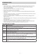
INTRODUCTION FEATURES xx Submersible Design – Complies with IPX8 submersible standards, which means the radio can be submerged in 1.5 meter of water for 30 minutes without damage. xx Large, dot matrix display xx Advanced DSC Class D functions, including Test Calling xx Channel select buttons on the microphone xx Memory scan mode – Lets you save channels to memory and monitor them in quick succession.
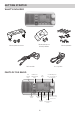
GETTING STARTED WHAT’S INCLUDED Mounting Hanger and Mounting Hardware Mounting Bracket and Knobs DC Power Cable Mounting Hardware Accessory Cable PARTS OF THE RADIO ENT 1W/25W button CHANNEL UP & CHANNEL DOWN button DISTRESS button LCD display CALL/MENU button CLR-SCAN (channel scan) button WX-MEM button 2 VOLUME-PWR (power knob - turn clockwise to increase volume) SQUELCH knob (turn clockwise to decrease channel noise 16/9-TRI (Triple/dual-watch button
Button ENT-1W/25W CHANNEL UP CHANNEL DOWN 16/9-TRI CLR-SCAN WX-MEM CALL-MENU DISTRESS Press to... Choose an option on a menu or to display the GPS data. Move up one channel at a time. Move down one channet at a time. 1st press: Go to Channel 16. Press and hold to... Change the transmit power (see page 12). Move quickly up the channels. 2nd press: Go to Channel 9. Go into Triple Watch or Dual Watch mode (see page 13). 3rd press: Go back to the original channel.
PARTS OF THE MICROPHONE Button (+) (-) 16/9-TRI SCAN/MEM Press to... Move up one channel at a time. Move down one channel at a time. 1st press: Go to Channel 16. 2nd press: Go to Channel 9. 3rd press: Go back to the original channel. Scan channels. Press and hold to... Move quickly up the channels. Move quickly down the channels. Push to Talk button Microphone Go into Triple Watch or Dual Watch mode (see page 13).
HOW IT WORKS Your radio has three basic modes of operation: Mode What It Does Use It When Normal Monitors a single marine radio channel and lets you talk on that channel. To Turn it on/ off... You want to talk to another station on a specific channel. (default mode) You have a small group of Monitors all the channels you use most often Press and hold the Scan channels you save into CLR-SCAN button. and want to check them for memory. traffic.
Message GPS Data OK Meaning The radio is receiving valid GPS data. The radio is not receiving valid GPS data: check the GPS status screen and the GPS connection. The radio has been unable to receive valid GPS data for at Input least four hours; it can no longer track your position. You need Position to manually input your position (see Setting the GPS position manually on page 14). Battery Low The battery voltage output is too low (below 10.5 VDC).
Normal mode with Triple or Dual Watch If you activate Triple Watch while operating in normal mode, the radio checks channels 16 and 9 every two seconds; with Dual Watch turned on, the radio only checks channel 16. The radio will not check channels 16 or 9 while you are actively transmitting; it waits until your transmission is finished and then checks the channels. Press and hold 16/9-TRI (on the radio or the microphone) for two seconds to turn Triple/ Dual Watch on or off.
In scan mode, you can get the following information from the display (some indicators will not always be displayed). Using the radio in scan mode xx You cannot transmit while in scan mode. xx You must have two or more channels in memory to start a scan. xx To save a channel into memory, select the channel, then press and hold WX-MEM for two seconds. Memory will show on the display. xx To remove a channel from memory, set the radio to that channel, then press and hold WX-MEM for two seconds.
Scan mode with Triple or Dual Watch If you activate Triple Watch while operating in scan mode, the radio checks channels 16 and 9 every two seconds, then goes on to scan the next channel; with Dual Watch turned on, the radio only checks channel 16. Press and hold 16/9-TRI (on the radio or the microphone) for two seconds to turn Triple or Dual Watch on or off. (To change between Triple or Dual Watch, see page 13.
Using the radio in weather mode xx You cannot transmit while in weather mode. xx To enter weather mode, press WX-MEM. xx Weather mode can filter out alerts that do not affect your location if the location code (FIPS code) of the alert is entered in your radio (see page 13). If you have no FIPS codes programmed into your radio, the radio will notify you of all alerts in any area. xx To turn off the radio’s alert tone, press any button.
CALL ENT 1W/2.5 W ENT 1W/2.5 W ENT 1W/2.5 W Using Your Radio xx An arrow on the left side indicates the current selection. xx Press CHANNEL UP on the radio or the microphone to move up a line in the menu; if you are at the top line in the menu, the cursor jumps to the bottom of the menu. xx Press ENT-1W/25W to choose the selected item. xx Press CHANNEL DOWN on the radio or the microphone to move down a line in the menu; if you are at the bottom line of the menu, the cursor jumps to the top of the menu.
While listening to a channel, adjust the SQUELCH knob until the noise is filtered out and you can only hear the transmission. If you switch to a channel with a lot of noise or with a weak transmission, you may need to adjust the squelch level again. ## NOTE: Setting the squelch level too high may prevent you from hearing weaker transmissions. If you are having difficulty hearing a transmission, try setting the squelch level lower.
Some channels (for example, channels 13 and 67) limit the power of transmission to 1 Watt so that there is less interference between boaters attempting to use the channel at the same time. If you switch to one of these channels, the radio changes back to 1 Watt automatically. See the channel lists beginning on page 37 for a list of power-restricted channels. Choosing Triple Watch or Dual Watch In Triple Watch mode, the radio briefly checks channels 16 and 9 every two seconds.
ENT 1W/2.5 W ENT 1W/2.5 W ENT 1W/2.5 W 1. 2. 3. 4. 5. 6. 7. 8. 9. Display the normal menu and choose the Setup sub-menu. Select FIPS Codes. The screen displays any previously-entered FIPS codes. To add a new FIPS code, select New. Use CHANNEL UP and CHANNEL DOWN to change the first of the six digits; CHANNEL UP increases the number and CHANNEL DOWN decreases it. When the first digit is correct, press ENT-1W/25W. The cursor moves to the next digit.
## NOTE: Be certain any manually-entered position is correct. If you enter the wrong position and then make a DSC distress call, you will be telling the arrows to adjust each of the values in turn. CALL ENT 1W/25W ENT 1W/25W ENT 1W/25W 1. Display the normal menu and choose the Setup sub-menu. 2. Select GPS Setup and then choose Position Set. 3. The GPS manual input screen displays; the fields to be entered blink. The cursor highlights the hour.
Feature Menu Item Function Contact another vessel from your Individual Call Individual directory. Contact all vessels that share your group Group Call Group MMSI code. Broadcast to all vessels within range (used All Ships Call All Ships for safety or advisory messages). Request the current location of another Position Request POS Request vessel. Transmit your current location to another Position Send Position Send vessel. Make sure your radio is working and Test Call Test configured correctly.
CALL ENT 1W/25W ENT 1W/25W ENT 1W/25W 1. Display the normal menu and choose the Setup sub-menu. 2. Select User MMSI. (If an MMSI number was already entered, the screen displays it with the message Cannot change over 1 time. Visit our website at www. unidensupport.com for help.) 3. Use CHANNEL UP and CHANNEL DOWN to enter the first of the nine digits; CHANNEL UP increases the number and CHANNEL DOWN decreases it. 4. When the first digit is correct, press ENT-1W/25W. The cursor moves to the next digit.
6. To save this MMSI number, select Yes and confirm the entry. To cancel this MMSI number, select No. The radio returns to the Setup menu. USING THE DIRECTORY The directory lets you store up to 20 MMSI numbers of other stations so you can call them quickly. CALL ENT 1W/25W ENT 1W/25W Follow the steps below to edit the MMSI numbers in your directory: 1. Press CALL-MENU to display the call menu. 2. Select Directory. The screen displays any previously-entered MMSI numbers and names. 3.
9. When you finish entering the name, the radio displays the new MMSI number and name and asks you to confirm. To save this directory entry, select Yes; to cancel this directory entry, select No. The radio returns to the directory list. 10. To change an existing directory entry, select the entry you want to change. 11. To delete the directory entry, select Delete. To edit the code, select Edit, then use CHANNEL UP and CHANNEL DOWN to edit the MMSI number and the name. 12.
Calling a single station (Individual Call) To call a single station with DSC, follow the steps below: 1. Press CALL-MENU to display the call menu. 2. Select Individual. 3. The radio displays the names listed in your directory; use CHANNEL UP and CHANNEL DOWN to choose the directory entry you want to call and press ENT-1W/25W. If you want to call a station that is not in your directory, select Manual. The radio prompts you to enter the MMSI number you want to call.
3. The radio prompts you to select a response channel. Use CHANNEL UP and CHANNEL DOWN to scroll through the available channels. When you reach the channel you want to use for a response, press ENT-1W/25W. 4. The radio asks you to confirm the call. Select Send to continue with the call or select Cancel to cancel the call. 5. The radio switches to channel 70 to transmit the call request then automatically switches to the designated response channel.
Canceling an automatic distress call While the radio is waiting for a response, it gives you the option of canceling the call. To cancel the distress call, choose Cancel and press ENT-1W/25W. RECEIVING A DSC CALL If your radio receives an individual DSC call from another station, it sounds an incoming call tone and displays the name or MMSI number of the station calling you.
DSC Call Type Distress Acknowledge Distress Relay Distress Relay Acknowledge Geographical All Ships Group Individual Individual Acknowledge Test Test Acknowledge Pos Reply Pos Request Pos Send Receive Log Information MMSI (or name), distress MMSI, position, time, nature code. MMSI (or name), distress MMSI, position, time, nature code. MMSI (or name), distress MMSI, position, time, nature code. MMSI (or name), category code, communication channel number.
Enter all nine digits and press ENT-1W/25W button. 4. The radio displays the MMSI number you are about to call and asks you to confirm. If you want to call the displayed number, select Send. To cancel the call, select Cancel. 5. The radio automatically switches to channel 70 to transmit the test call request, then switches back to the last-used channel. 6. When the other station acknowledges the test call, the radio displays an acknowledgement screen.
3. To disable automatic test call reply, repeat the steps above and select Manual. POSITION REQUEST AND REPLY Requesting another station’s position (POS Request) Anytime you need to know where another boat currently is—to find your boating partners, to respond to a request for assistance, etc.—you can send a position request to their radio: 1. Press CALL-MENU to display the call menu. 2. Select DSC Call sub-menu, then select POS Request. 3.
Enabling automatic position reply If you want the radio to automatically transmit your current position whenever it receives a position request, you can enable automatic position reply. Most boaters activate automatic position reply for safety reasons or because they subscribe to a marine towing service. Sometimes—for example, in some competitive situations--you may not want other stations to get your position without your manual confirmation 1. Press and hold CALL-MENU to display the normal menu. 2.
3. To cancel standby and return to the mode your radio was in, press any button. DISABLING AUTOMATIC CHANNEL SWITCHING If you are involved in a bridge-to-bridge call, you may not want the radio to automatically switch channels when it receives a DSC call. In cases like this, you can disable automatic channel switching. If you receive an individual call, the radio will respond with an unattended code, just as if the radio were in Standby. 1. Press and hold CALL-MENU to display the normal menu. 2.
INSTALLING THE HARDWARE MOUNTING THE RADIO Your radio can sit at any angle in the mounting bracket so it can easily accommodate the best location. First, determine the best place to mount the radio. For optimum performance, find a location that can: xx Properly support the weight of the radio, approximately 2.2 pounds or 1.0 kilograms. You may need to use some type of anchor with the mounting screws to hold the radio, depending on the surface. xx Keep the battery leads as short as possible.
CONNECTING THE RADIO To operate correctly, your radio requires two electrical connections: xx providing it with power from the boat’s electrical system xx connecting a VHF-FM marine antenna to the antenna connector Power Supply Requirements VHF Antenna Requirements Male PL-259 connector Nominal 13.8 VDC power supply with a negative ground (10.5 VDC to 16.0 VDC). 50 Ω impedance Power leads should be kept as short as Minimum 3 foot, 3 dB rated antenna for possible.
CONNECTING THE ACCESSORY CABLE Use the accessory cable to connect the radio to a GPS receiver, a GPS chartplotter, and an external speaker. The wiring diagram below shows the connections for each accessory. ACCESSORY CABLE WIRES CONNECTS TO...
After 4 hours, the audible alert sounds again if no coordinates are received and the GPS is connected. After 23.5 hours, the radio deleted the current coordinates and displays Input GPS. See page 14 to manually set the GPS coordinates. Configuring the GPS If the radio is receiving valid GPS data, it will automatically set the clock to your local time based on the GPS location.
CONNECTING TO AN EXTERNAL SPEAKER You can use an external speaker to monitor the radio from a different part of your boat or in a noisy environment. If you adjust the VOLUME-PWR knob on the radio, it will also adjust the external speaker volume. Your radio supports an external speaker with the following specifications: xx Minimum impedance of 4 Ohms xx Minimum power handling of 10 Watts 1. Connect the BLACK wire of the accessory cable to the GROUND WIRE of your external speaker. 2.
MAINTENANCE AND TROUBLESHOOTING Due to its rugged design, your radio requires very little maintenance. However, it is a precision electronic instrument, so you should follow a few precautions: xx If the antenna has been damaged, you should not transmit except in the case of an emergency. A defective antenna may cause damage to your radio. xx You are responsible for continued FCC technical compliance of your radio. xx You should arrange for periodic performance checks with your dealer.
Problem Things to Try Make sure your GPS receiver is correctly connected (see Connecting to a GPS receiver, page 30). I’m not getting any GPS data on my display. Make sure your GPS receiver is working properly. I’m not getting any hazard alerts. Check to make sure the FIPS codes in your radio include your current location (see Using FIPS codes for weather alerts on page 13). Check to make sure the FIPS codes in your radio were entered correctly (see Using FIPS codes for weather alerts on page 13).
SPECIFICATIONS All specifications are subject to change without notice.
General Sensitivity Circuit Squelch Sensitivity Spurious Response Adjacent Channel Selectivity Audio Output Power Power Requirement IF Frequencies 0.25 μV for 12 dB SINAD (nominal) Dual Conversion Super Heterodyne PLL (Crystal for DSC) 0.2 μV Threshold 75 dB (nominal) 70 dB @ ±25 kHz (nominal) 2.5 watts (10% Distortion, 8 Ω load) 360 mA @ 13.8V DC at squelched, 920 mA @ 13.8V DC at maximum audio output 1st 41.925 MHz, 2nd 455 kHz (1st 21.
Channel name/description STATE CONTROL DIGITAL SELECTIVE CALLING Used for messages about government regulation and control, boating activities, or assistance to ships; also used to talk to ships and coast stations operated by state or local governments DSC signals only (no voice communications allowed at any time) MARINE RADIO CHANNEL CHART Ch No. USA 01 01A* INT x CAN TX x x RX 156.050 160.650 156.050 156.050 02 x x 156.100 160.700 03 x x 156.150 160.750 04 x 156.200 160.800 156.
Ch No. USA 13 x x x 156.650 156.650 14 x x x 156.700 156.700 15 x Inhibit 156.750 15 INT CAN TX RX x x 156.750 156.750 16 x x x 156.800 156.800 17 x x x 156.850 156.850 156.900 161.500 x 156.900 156.900 x 156.950 156.950 161.550 156.950 x 157.000 161.600 157.000 157.000 x 157.050 157.050 161.650 157.050 x INHIBIT 161.650 157.100 161.700 x 157.100 157.100 x 157.150 161.750 157.150 157.150 x INHIBIT 161.
Ch No. USA INT 26 x x x 157.300 161.900 27 x x x 157.350 161.950 28 x x x 157.400 162.000 x INHIBIT 162.000 x 156.025 160.625 156.075 160.675 156.075 156.075 156.125 160.725 156.125 156.125 156.175 160.775 x 156.175 156.175 x 156.225 160.825 x 156.225 156.225 156.275 160.875 156.275 156.275 156.325 160.925 x 156.325 156.325 28B 60 x 61 x 61A x 62 x 62A x 63 63A x x 64 x 64A 65 65A CAN TX x x 66 x x RX 66A x 67 x x x 156.
Ch No. USA INT 69 x x x 156.475 156.475 70 x x x 156.525 156.525 71 x x x 156.575 156.575 72 73 74 75 76 77 78 78A 79 79A 80 80A 81 x x x x x x x x x x x x x x x x x x x 156.625 156.675 156.725 156.775 156.825 156.875 156.925 156.925 156.975 156.9750 157.025 157.025 157.075 156.625 156.675 156.725 156.775 156.825 156.875 161.525 156.925 161.575 156.975 161.625 157.025 161.675 157.075 157.075 157.125 161.725 x 157.125 157.125 x 157.175 157.175 161.775 157.
Ch No. USA INT 88A x x 157.425 157.425 1019 1020 1078 1079 2019 2020 2078 2079 x x x x x x x x x x x x 156.950 157.000 156.925 156.975 161.550 161.600 161.525 161.575 156.950 157.000 156.925 156.975 161.550 161.600 161.525 161.575 CAN TX RX Channel Type/Name Public Correspondence (Marine Operator) Commercial Port Operations Non-Commercial, Inter-Ship Commercial, Inter-Ship Commercial Port Operations Port Operations Port Operations WEATHER CHANNELS AND FREQUENCIES (US, CAN, AND INT) Ch No.
SAME Code BZW CFA CFW DSW FFA FFW FFS FLA FLW FLS HWA HWW HUA HUW HLS SVA SVR SVS SMW SPS TOA TOR TRA TRW TSA TSW WSA WSW NIC AVA AVW CAE CDW CEM EQW EVI FRW HMW LEW Event Blizzard Warning Coastal Flood Watch Coastal Flood Warning Dust Storm Warning Flash Flood Watch Flash Flood Warning Flash Flood Statement Flood Watch Flood Warning Flood Statement High Wind Watch High Wind Warning Hurricane Watch Hurricane Warning Hurricane Statement Severe Thunderstorm Watch Severe Thunderstorm Warning Severe Weather St
Event Local Area Emergency 911 Telephone Outage Emergency Nuclear Power Plant Warning Radiological Hazard Warning Shelter in Place Warning Volcano Warning Test Message Practice/Demo Warning Required Monthly Test Required Weekly Test Biological Hazard Warning Boil Water Warning Chemical Hazard Warning Dam Watch Dam Break Watch Contagious Disease Warning Emergency Action Notification Emergency Action Termination Evacuation Watch Flood Contamination Warning Flash Freeze Warning Iceberg Warning Industrial Fire
TXO TXP Transmitter Carrier On Transmitter Primary On NMEA OPERATION This radio supports NMEA0183 version 3.01. NMEA Input If you have difficulty getting your radio to receive data from your GPS receiver, check the device’s configuration. It should be set to the following parameters: Baud rate Data bits Parity Stop bits Data amplitude Drive capability 4800 bps 8 None 1 Over 3.0 V Over 10 mA The radio supports RMC, GLL, GNS, GGA and ZDA sentences.
REGULATIONS AND SAFETY WARNINGS MARITIME RADIO SERVICES OPERATION WARNING! This transmitter will operate on channels/frequencies that have restricted use in the United States. The channel assignments include frequencies assigned for exclusive use of the U.S. Coast Guard, use in Canada, and use in international waters. Operation on these frequencies without proper authorization is strictly forbidden. See the channel tables beginning on page 37 for a list of available channels and their uses.
IC This device complies with Industry Canada license-exempt RSS standard(s). Operation is subject to the following two conditions: (1) this device may not cause interference, and (2) this device must accept any interference, including interference that may cause undesired operation of the device. Changes or modifications not expressly approved by the party responsible for compliance could void your authority to operate the equipment.
(E) used in any conjunction with equipment or parts or as part of any system not manufactured by Uniden, or (F) installed or programmed by anyone other than as detailed by the Operating Guide for this product.