
Specifications
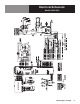
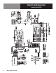


OM-HY/3E(CE) & HY/5E(CE) 27
• Using four hex/slotted 6-32 screws, screw the motor mounting plate to the
motor with each screw passing through corresponding holes in the plate seal
holder.
• The entire assembly may now be positioned on the four threaded stud bolts
protruding from the cavity wall. Fasten the assembly with the 1/4-20 kep
nuts using a 7/16 inch nut driver. Make sure that the green ground strap is
fastened by one of the kep nuts securing the motor.
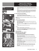
10. Motor Starting Capacitor (P/N 096813)
• Turn off electrical power to the steamer.
• Loosen the two screws holding the motor capacitor.
• Unplug the two terminal wires from the capacitor. Remove the capacitor.
NOTICE: Make sure that the correct value of capacitor is used, which is 3 µfd with
a 330 volt rating.
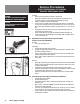
11. Control Transformer (P/N 106234)
• Turn off power to the steamer.
• Note the position and identity of the terminals and then remove them from
the control transformer.
• With a 5/16 inch nutdriver, remove the four 10-32 screws holding the control
transformer to the service tray. NOTE: Do not lose lock washers at the ground
wire.
• Remove control transformer from the service tray.
To Install:
• Install the control transformer in the service tray.
• Fasten the control transformer to the service tray with four 10-32 screws
using a 5/16 inch nutdriver. NOTE: Ground terminal between lock washers.
• Reattach terminals to control transformer.
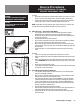
12. Gasket (P/N 042366)
Heater Element (P/N 123102 - 240 Volt)
High Limit Thermostat (P/N 122009)
• Turn off all power to the steamer.
• Remove the six terminals and two plugs from the heating element.
• With a 1/2 inch socket wrench, remove the four nuts and lockwashers
holding assembly to generator.
• Carefully slide the assembly about 2 inches out of the steam generator.
• Remove the two 6-32 self tapping sheet metal screws from the underside of
the thermostat switch.
• Remove the two terminal wires attached to the thermostat Electric Heater
Assembly switch.
• Remove the gasket attached to the steam generator and discard. Remove
heater and thermostat assembly.
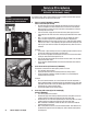
• The thermostat bulb is fastened to one of the heater elements by two small
hose clamps or metal straps.
• Remove the clamps or straps holding the thermostat bulb to the heater.
• With a 9/16 inch open-ended wrench, loosen the capillary fitting for the
thermostat.
• Remove the probe, capillary and thermostat bulb as an assembly.
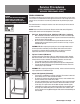
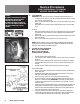
Service Procedures
[FOR PROFESSIONAL TECHNICAL
SERVICE PERSONNEL ONLY]
Fan Motor Capacitor
Control Transformer
WARNING
DISCONNECT THE POWER SUPPLY BEFORE
BEGINNING ANY SERVICE PROCEDURE.
Electric Heater Assembly - High Limit
Thermostat Switch Box Mounted Above