2YEARS Warranty (Power Source) 240 Volt L OPERATING MANUAL KUMJR200AC/DC Please read and understand this instruction manual carefully before the installation and operation of this equipment.
Thank you for your purchase of your UNI-MIG welding machine. We are proud of our range of welding equipment that has a proven track record of innovation, performance and reliability. Our product range represents the latest developments in Inverter technology that have been implemented by our professional team of highly skilled engineers. The expertise gained from our long history of sales has proven to be invaluable to the evolution and future development of our equipment range.
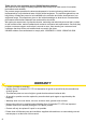
CONTENTS PAGE Warranty 2 Safety - Cautions 4-6 Technical Data, Product Information 7 Machine Layout & Descriptions 8 Front Panel Selector Switch Function Descriptions 9 Front Panel Control Dial Function Descriptions 10-11 Machine Installation & Operation 13 Installation & Operation for MMA (Stick) Welding 14-15 MMA (Stick) Welding 16-17 Installation & Operation for DC TIG Welding 18-19 DC TIG Welding, DC Pulse TIG Welding 20-22 TIG Welding Fusion and Filler Wire Technique 23 Instal
SAFETY Welding and cutting equipment can be dangerous to both the operator and people in or near the surrounding working area, if the equipment is not correctly operated. Equipment must only be used under the strict and comprehensive observance of all relevant safety regulations. Read and understand this instruction manual carefully before the installation and operation of this equipment. Machine Operating Safety • Do not switch the function modes while the machine is operating.
Fire hazard. Welding on closed containers, such as tanks,drums, or pipes, can cause them to explode. Flying sparks from the welding arc, hot work piece, and hot equipment can cause fires and burns. Accidental contact of electrode to metal objects can cause sparks, explosion, overheating, or fire. Check and be sure the area is safe before doing any welding. • The welding sparks may cause fire, therefore remove any flammable materials away from the working area, at least 12m from the welding arc.
CAUTION 1. Working Environment. 1.1 The environment in which this welding equipment is installed must be free of grinding dust, corrosive chemicals, flammable gas or materials etc, and at no more than maximum of 80% humidity. 1.2 When using the machine outdoors protect the machine from direct sun light, rain water and snow etc; the temperature of working environment should be maintained within -10°C to +40°C. 1.3 Keep this equipment 30cm distant from the wall. 1.
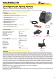
KUMJR200AC/DC Certified - AS/NZ60974.
Front Machine Layout Description Amperage Display Function Alarm LED Thermal Alarm LED Gas Pre Flow Control Dial Peak Current Control Dial Base Current Control Dial Remote Control Selector ON/OFF Switch Down Slope Control Dial TIG/MMA Selector Post Flow Gas Control Dial 2T/4T Selector AC Balance Control Dial AC/DC Selector Pulse Width Control Dial Pulse Frequency Control Dial Pulse Selector Negative Output Terminal Arc Force Control Dial Gas Out Connector Torch Switch Socket Foot Amp Contro
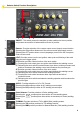
Selector Switch Function Descriptions 3 1 2 4 5 6 1 ON/OFF: This switch powers the machine up when switched to the on position and powers the machine off when switched to the off position. 2 Remote: Provides selection of the remote output current (amps) control function Selecting the ON position allows use of the remote current (amperage) controls Selecting the OFF postion allows current (amperage) control from the front panel Peak current control.
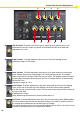
Control Dial Function Descriptions A E 10 B F C G D H I A Gas Pre Flow: Provides a pre-flow of gas to purge tig torch gas line prior to the initialisation of the arc. Helps arc ignition and prevents porosity in the weld start. Adjustment is 0-1sec. B Peak Current: Provides adjustment and control of the main welding current. Adjustment range 10-200 Amps. C Base Current: Provides adjustment and control of the base welding current during pulse welding.
Control Dial Function Descriptions - continued F Pulse Frequency: Provides adjustment and setting of the pulse frequency when the machine is set in Pulse mode. It adjust the amount of times per second (Hz) the output current switches from the Peak current setting to Base current setting. Adjustment is 0.5-300Hz. G Pulse Width: Provides adjustment and setting of the on time for the Peak current during a pulse cycle.
INSTALLATION & OPERATION Please install the machine strictly according to the following steps. The protection class of this machine is IP21S, so avoid using it in rain. Connection of Input Cables Primary input cable is supplied with this welding equipment. Connect the primary input cable with power supply of required input voltage. Refer to data plate on machine for Input voltage, IMAX and IEFF.
Installation set up for MMA (Stick) Welding with KUMJR200AC/DC (1) Turn the power source on and select the MMA function with the Tig/MMA selector switch. (2) Connection of Output Cables Two sockets are available on this welding machine. For MMA welding the electrode holder is shown be connected to the positive socket, while the earth lead (work piece) is connected to the negative socket, this is known as DC+ polarity.
continued set up and operation for MMA (Stick) Welding (3) Set the welding current relevant to the electrode type and size being used as recommended by the electrode manufacturer (4) Place the electrode into the electrode holder and clamp tight (5) Strike the electrode against the workpiece to create and arc and hold the electrode steady to maintain the arc (6) Hold the electrode slightly above the work piece to maintain the arc while travelling at an even speed to create and even weld deposition (7) To fin
MMA (Manual Metal Arc) Welding General Description One of the most common types of arc welding is manual metal arc welding (MMA) or stick welding. An electric current is used to strike an arc between the base material and a consumable electrode rod or ‘stick’.
MMA (Stick) Welding Fundamentals Electrode Selection As a general rule, the selection of an electrode is straight forward,in that it is only a matter of selecting an electrode of similar composition to the parent metal. However, for some metals there is a choice of several electrodes, each of which has particular properties to suit specific classes of work. It is recommended to consult your welding supplier for the correct selection of electrode.
Installation set up for DC TIG Welding with KUMJR200AC/DC (1) Turn on the machine using the ON/OFF switch (2) Select the TIG function with the TIG/MMA selector switch. (3) Select DC using the AC/DC selector switch. (4) Connect the Tig Torch connector to the negative terminal and tighten it. (5) Connect the Earth Cable connector into the positive terminal and tighten it.
DC HF TIG Operation with KUMJR200AC/DC HF (high frequency) ignition allows the arc to be started in Tig welding without touching the tungsten to the work piece. By pressing the torch switch the machine will activate the gas flow and the HF ignition resulting in the arc igniting across the gap between the tungsten electrode and the work piece. The distance between the electrode and the work piece can be up to 5mm.
DC TIG Welding General Description 30% 70% The DC power source uses what is known as DC (direct current) in which the main electrical component known as electrons flow in only one direction from the negative pole (terminal) to the positive pole (terminal). In the DC electrical circuit there is an electrical principle at work which should always be taken into account when using any DC circuit. With a DC circuit 70% of the energy (heat) is always on the positive side.
DC Pulse TIG Welding General Description Pulse TIG welding is when the current output (amperage) changes between high and low current. Electronics within the welding machine create the pulse cycle. Welding is done during the high-amperage interval (this high amperage is referred to as peak current). During the low amperage period, the arc is maintained but the current output of the arc is reduced (this low amperage is referred to as base current).
EXAMPLE 1 OF PULSE DC TIG WELDING - SETUP PARAMETERS: Material = Stainless Steel x 2.0mm / Tungsten Electrode = 1.6mm 2% Thoriated / Gas = Argon The following steps are a guide as a starting point for you to set the machine up in Pulse mode to give an example of welding in Pulse mode function.
TIG Welding Fusion Technique Manual TIG welding is often considered the most difficult of all the welding processes. Because the welder must maintain a short arc length, great care and skill are required to prevent contact between the electrode and the workpiece. Similar to Oxygen Acetylene torch welding, Tig welding normally requires two hands and in most instances requires the welder to manually feed a filler wire into the weld pool with one hand while manipulating the welding torch in the other.
Set up and operation for AC TIG Welding - KUMJR200AC/DC (1) Turn on the machine using the ON/OFF swicth (2) Select the TIG function with the TIG/MMA selector switch. (3) Select AC using the AC/DC selector switch. (4) Connect the Tig Torch connector to the negative terminal and tighten it. (5) Connect the Earth Cable connector into the positive terminal and tighten it. (6) Connect the torch switch remote lead into the torch remote socket (7) Insert the torch gas connector into the quick lock gas receptacle.
continued - Set up and operation for AC TIG Welding - KUMJR200AC/DC AC (alternating current) enables us to TIG weld non ferrous alloys like Aluminium, Aluminium Alloys and Magnesium. These materials have an insulating surface oxide layer that melts at a higher temperature than the base metal making it difficult to weld the base metal if the oxides are not removed. AC welding current is ideal because the nature of the AC wave form assists in breaking the surface oxide layer.
AC Welding AC (alternating current) enables us to TIG weld non ferrous alloys like Aluminium, Magnesium and Aluminium Alloys. These materials have an insulating surface oxide layer that melts at a higher temperature than the base metal making it difficult to weld the base metal if the oxides are not removed. AC welding current is ideal because the nature of the AC wave form assists in breaking the surface oxide layer.
In older machines, a balanced current output wave was achieved using a large number of capacitors in series or a battery in the welding circuit. Modern TIG power sources use electronics to create and maintain a balanced wave and now most AC TIG power sources produce a square wave current output. direct polarity current reverse polarity A square wave power supply can change the current from electrode + positive to electrode - negative very quickly.
EXAMPLE 1: PULSE AC TIG WELDING - SETUP PARAMETERS: Material = Aluminium x 3.0mm / Tungsten Electrode = 2.4mm Zirconiated / Gas = Argon The following steps are a guide as a starting point for you to set the machine up in AC Pulse mode to give an example of welding in AC Pulse TIG function.
Remote Amperage Controls - Installation and Operation Remote amperage controls allow for the welding current to adjusted remotely from the welding machine during welding. Generally there several types of remote amperage control available; (1) Hand amperage control located in the torch handle allowing the operator to adjust the welding current by rolling the potentiometer wheel to increase or decrease the amount of amperage desired.
Tungsten Electrodes Tungsten is a rare metallic element used for manufacturing TIG welding electrodes. The TIG process relies on tungsten’s hardness and high-temperature resistance to carry the welding current to the arc. Tungsten has the highest melting point of any metal, 3,410 degrees Celsius. Tungsten electrodes are nonconsumable and come in a variety of sizes, they are made from pure tungsten or an alloy of tungsten and other rare earth elements.
Tungsten Preparation Always use DIAMOND wheels when grinding and cutting. While tungsten is a very hard material, the surface of a diamond wheel is harder, and this makes for smooth grinding. Grinding without diamond wheels, such as aluminium oxide wheels, can lead to jagged edges, imperfections, or poor surface finishes not visible to the eye that will contribute to weld inconsistency and weld defects. Always ensure to grind the tungsten in a longitudinal direction on the grinding wheel.
Tungsten preparation AC Welding To obtain full current capacity from a pure or zirconiated tungsten electrode when used with AC current output the electrode is not ground to a point. The welding during positive polarity melts the point of the tungsten that becomes rounded. The ball shape formed at the end of the tungsten is desirable because it reduces current rectification and allows the arc to flow more easily.
MMA (Stick) WELDING TROUBLE SHOOTING The following chart addresses some of the common problems of MMA welding. In all cases of equipment malfunction, the manufacturer’s recommendations should be strictly adhered to and followed. 1: No arc Possible Reason Suggested Remedy Incomplete welding circuit Check earth lead is connected. Check all cable connections.
TIG WELDING TROUBLE SHOOTING The following chart addresses some of the common problems of TIG welding. In all cases of equipment malfunction, the manufacturer’s recommendations should be strictly adhered to and followed. 1: Tungsten burning away quickly Possible Reason Suggested Remedy Incorrect Gas Check that pure Argon is being used No gas Check the gas cylinder contains gas and is connected Inadequate gas flow Check the gas is connected, check hoses, gas valve and torch are not restricted.
6: HF present but no welding power Possible Reason Suggested Remedy Incomplete welding circuit Check earth lead is connected. Check all cable connections. If using a water cooled torch check that the power cable is not separated. No gas Check the gas is connected and cylinder valve open, check hoses, gas valve and torch are not restricted. Set the gas flow between 10 - 15 l/min flow rate Tungsten melting into the weld pool Check that correct type of tungsten is being used.
UNI-FLAME AUTOLIFT UNI-FLAME Suregrip Series SR26 ERGO TIG TORCH 200A AIR COOLED TIG WELDING TORCH Rating:200Amp DC, 140Amp AC @35% duty cycle.
UNI-FLAME AUTOLIFT SR26 ERGO TIG TORCH UNI-FLAME Suregrip Series Standard Front End Parts Part # 18CG Description Cup Gasket Part # 10N30 10N31 10N32 10N28 Part # 10N22 10N23 10N24 10N25 Description Collet Body 1.0mm Collet Body 1.6mm Collet Body 2.4mm Collet Body 3.2mm Description Collet 1.0mm Collet 1.6mm Collet 2.4mm Collet 3.
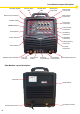
Spare Parts Identification 1 18 2 19 15 3 4 5 6 7 8 16 21 20 17 9 10 11 12 13 14 24 23 22 25 32 26 27 28 29 30 31 34 35 36 33 37 38 39 40 37
Spare Parts Identification 38 1 2 3 4 5 6 7 8 9 10 11 12 13 14 15 16 17 Part Number J10A10 D20006 C16017 B22310 B22329 B22311 B22330 B22328 C02066 J24011 J21009 C04022 C04023 C04045 C14021 P00706 C02066 Description Front Plastic Panel Digital Display Meter On/Off Switch Remote Control Selector Switch 2T/4T Trigger Selector Switch Tig/MMA Selector Switch AC/DC Selector Switch Pulse Mode Selector Switch Panel Socket 35-50 Rubber Foot Gas Connector Quick Fit - Female Panel Mount 2 Pin Connector - Female Pa
Welding Guns Of Australia Pty Ltd WARRANTY CARD Welding Guns Of Australia Pty Ltd (‘Us’, ‘We’) warrants that the following products under UNI-MIG, UNI-TIG, UNI-PLAS, UNI-FLAME, XCEL-ARC, TECNA, T&R, HIT-8SS & ROTA, supplied by Us and purchased by you from an Authorised UNI-MIG, UNI-TIG, UNI-PLAS, UNI-FLAME, XCEL-ARC, TECNA, T&R, HIT-8SS & ROTA Dealer throughout Australia are free of Material and Faulty Workmanship defects except for those products listed under ‘Warranty Exclusions’.
WARRANTY / RETURNS / EXCHANGES We understand that sometimes you may need to return a product you have purchased from Welding Guns Of Australia PTY LTD Authorised Dealer Network, to assist you, we have set out below the Welding Guns Of Australia PTY LTD Returns Policy that you should know. Our Returns Policy includes the rights you have under the Australian Consumer Law and other relevant laws.
© Welding Guns Of Australia PTY LTD 2012 UNI-FLAME AUTOLIFT UNI-FLAME Welding Guns Of Australia Pty Ltd ABN: 14 001 804 422 PO Box 3033, Lansvale NSW 2166, AUSTRALIA 112 Christina Rd, Villawood, NSW 2163 Phone: (02) 9780 4200 Fax: (02) 9780 4244 Email: sales@unimig.com.au / Web: www.unimig.com.