PK-100N PK-400N Service Manual * This Service manual is subject to change according to improvement of PK-Series Portable Radio without notice.
Read this information before using your product. Acknowledging Special Precautions and the FCC Notice Cautions. Modifications not expressly approved by the party responsible for compliance could void the user's authority to operate the equipment. FCC compliance Information This device complies with part 15 of FCC Rules. Operation is subject to the following two conditions: 1. This device may not cause harmful interference, and 2. This device must accept any interference received.
1. RADIO FREQUENCY ENERGY SAFETY INFORMATION This UNIMO transceiver has been tested and complies with the standards listed below, in regards to radio Frequency(RF) energy electromagnetic energy(EME) generated by the transceiver > FCC RF exposure limits for Occupational use only. RF exposure limits adopted by the FCC are generally based on recommendations from the national council on radiation protection and measurement, & the American National National Standards Institute.
Use only UNIMO authorized accessories (antennas, battery packs, belt clips, Speaker/Mics or headsets etc.): When worn on the body, always place the radio in a UNIMO recommended clip or carrying case meant for this product. The use of other than recommended or approved body-worn accessories may result in RF exposure levels which exceed the FCC's occupational /controlled environment RF exposure limits.
2. Features The features of PK-series are various as below. PK-series can be used under tough industrial environments as well as public places. PK series have following functions: -. PLL synthesizer method -. 256 channels and 16 groups are selectable. -. Call guard squelch of the standardized DCS/CTCSS -. Dual Tone Modulation Frequency (DTMF) -. 2/5-tone paging -. Channel interval: 12.5kHz -. Normal scanning and priority scanning -. Time-Out Timer (TOT) -. BCL/BCLO -. Paging -. Wide-band -.
) 256 Channels and 16 Groups Selectable Users can use various tones with 47 CTCSS and 83 DCS . 256 channels can be divided into 16 groups so that users can make group for other users and page each group. 7) Multi-functional Ear/MIC Jack With multi-functional Ear/MIC Jack, it is possible to be used together with various accessories. 8) Cloning For compatibility with current models of UNIMO, the data of those models (such as channels, tones, 5-tone ID, etc.) are cloned to another radio with Cloning cable. .
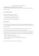
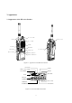
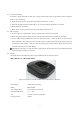
3. Appearance 3.1 Appearance of the PK-series Product On / Off Volume Battery Locker Antenna Rx / Tx Lamp Speaker PTT Button Microphone Ear / Mic jack Menu Button Display LCD Monitor Button Channel Up Button Channel Down Button Figure 3.1. Appearance of the PK-series Product CTC/DCS TWO / FIVE TONE TX POWER SCAN ALERT BATTERY RSSI GROUP NUMBER KEY LOCK CHANNEL NUMBER VOX MODE Figure 3.2.
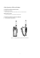
4. Basic Operation of PK-series Products 4.1 Installation and Removing the Antenna 1) Installation the Antenna Insert the antenna screw into the antenna hole, and screw the antenna clockwise. 2) Removing the Antenna To remove the antenna, screw the antenna counterclockwise. 4.2 Installation and Removing PK-series Batteries 1) Inserting and Removing the Battery Figure 4.1.
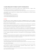
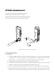
4.3 The Radio disassembling method First, please remove the battery, Volume Knob and Antenna. And please pull up Ear Phone Jack Cover with hands. As showing picture as below, stick to the bottom holes by using Jig. By moving up Jig and pull it to the direction of disassembling. (X) (O) Figure 4.2. Radio disassembling method 4.4 Charging the Battery 1) Safety Notes 1) The radio of UNIMO Technology receives power from high-performance Li-ion battery (only for PK Series) or Ni-MH battery.
2) The time of Charging Low battery voltage will make the radio less coverage and also make worse the performance. Please charge the battery in case of following: ① When the battery has lower performance after being used around 6 ~ 8 hours ② When the red lamp on the front panel blinks (every 0.
5. Operating Instructions of PK-Series Radio 5.1 Power On/Off Turn Power switch clockwise. As soon as power is supplied, the backlight will be turned on. If the user had set up the user ID and the name, they will be displayed on the LCD and the radio will enter into the latest state as a signal sound is generated.
Indicator (RSSI). If the communication conditions is poor or the tone (CTCSS/DCS) is not the same even though the frequency is the same, the user needs to press Monitor button (M) on the left side of the radio to receive all signals of the current channel. However, if the user presses Monitor button (M) under normal circumstances, the user will only hear noise. To keep this feature on, the user needs to presses Monitor button for a while (2 seconds).
5.8 Selective Call (Paging) In Selective Call mode (Paging mode), the user can call individuals and groups through the 5-tone ID. Each Selective Call memory (paging memory) stores up to 30 IDs and names. The user should set the paging memory and the 5-tone environment in the PC program. To enter into Selective Call (Paging mode), press “Menu” and “M” button , and to go back to Normal mode, press “Menu” button for two seconds in Selective Call (Paging mode).
③ Only the radio which is in the status of selective call and receive the same ID with its own could receive the audio signal 3) Group (1:N) Call in Selective Call Mode (Paging Mode) ① To call a group in Selective Call Mode (Paging mode), the user needs to set the group in the PC program as follows: ② If JOHN (13579) and JANE (12468) belong to one group, allocate a paging number (1AAAA) and a name (COMPANY) to the group. (“A” represents All and can be any number.
is not used. 5.11 Change Groups The radio of UNIMO have total 256 channels with 16 groups, and the user can set each group and channel by the PC program or by the menus. ① Enter into Menu mode. ② Select “Group” by pressing Channel buttons (▲ and ▼), and press “Menu”. Then, the message of the selected group will be displayed. ③ Change the group by pressing Channel buttons (▲ and ▼), and save the changed group by pressing “Menu” button. ④ Exit Menu mode by pressing “M”s button.
5.13 ID Display ID Display function is to send the caller’s ID and it display Caller’s ID on the called person’s radio. The ID is mainly divided into DTMF and 5 tones. Especially, 5 tones are to send the caller’s ID to the other person’s radio and display the caller’s ID on the called person’s radio for convenient and efficient use of the radio. ① Enter into Menu mode. ② Select “Id” by pressing Channel buttons (▲ and ▼) and press “Menu” button.
④ Exit Menu mode by pressing “M”s button. Select “Off”. Then, the bell symbol will disappear on the LCD. 5.15 Scan Scan is to search channels registered in the scan list and let the radio select the channel automatically in which a signal is received. To use Scan menu, the user first needs to set the scanning feature for the corresponding channel in the PC program: ① Enter into Menu mode. ② Select “Scan” by pressing Channel buttons (▲ and ▼) and press “Menu” button.
5.16 Set Key Lock Set Key Lock menu avoids 3 buttons(Menu, ▲ and ▼) is functioned by undesired pressing. After setting Key Lock menu, all buttons will not be functioned by pressing buttons. ① Enter into Menu mode. ② Select “Lock” by pressing Channel buttons (▲ and ▼) and press “Menu”. Then, Key Pressing Lock message will be displayed. ③ Select On or Off by pressing Channel buttons (▲ and ▼), and save the selected status by pressing “Menu” button. ④ Exit Menu mode by pressing “M”s button. Select “Off”.
5.17 Set Password Set Password is to prevent the other people from using the radio by setting a password. The user should type in the correct password to use the radio. ① Enter into Menu mode. ② Select “Secret” by pressing Channel buttons (▲ and ▼) and press “Menu” button. Then, “New Password” will be displayed. Or if the user had set the password already, Password will be displayed.
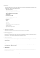
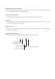
Blank Blank Yes Menu M Yes Menu No M No Menu Menu Menu M Menu Menu M M M Menu M Figure 5.18 SET Forbid Tx Figure 5.
6. Sub-tone Table 6.1 CTCSS Frequency Table No. Frequency No. Frequency No. Frequency 001 67.0 017 118.8 033 210.7 002 71.9 018 123.0 034 218.1 003 74.4 019 127.3 035 225.7 004 77.0 020 131.8 036 233.6 005 79.7 021 136.5 037 241.8 006 82.5 022 141.3 038 250.3 007 85.4 023 146.2 039 69.3 008 88.5 024 151.4 040 159.8 009 91.5 025 156.7 041 183.5 010 94.8 026 162.2 042 189.9 011 97.4 027 167.9 043 196.6 012 100.0 028 173.8 044 199.
17 116 45 343 73 654 18 125 46 346 74 662 19 131 47 351 75 664 20 132 48 364 76 703 21 134 49 365 77 712 22 143 50 371 78 723 23 152 51 411 79 731 24 155 52 412 80 732 25 156 53 413 81 734 26 162 54 423 82 743 27 165 55 431 83 754 28 172 56 432 Table 6-2. CDCSS Frequency Table 6.
7. Specification 7.1 PK-100N General Operating Mode Conventional (non-trunked) only Frequency Range VHF: 136 Frequency Stability ±2.5PPM (-30 to +60℃) Programmable Channels 128 Channels/16 Group Channel Spacing Dual Channel Spacing 12.5KHz Dimensions 111mm (H)×54mm (W)×37mm (D) Weight 347g (with Battery pack & Antenna) Power Source 7.5V DC rechargeable Ni-MH 1650㎃ battery pack ~ 174 MHz 7.
7.2 PK-400N General Operating Mode Conventional (non-trunked) only Frequency Range UHF: 400 Frequency Stability ±2.5PPM (-30 to +60℃) Programmable Channels 128 Channels/16 Group Channel Spacing Dual Channel Spacing 12.5KHz Dimensions 111mm (H)×54mm (W)×37mm (D) Weight 347g (with Battery pack & Antenna) Power Source 7.5V DC rechargeable Ni-MH 1650㎃ battery pack ] 7.
8. Troubleshooting Flow 8.1 Reception Trouble Start ↓ Reception is not made. ↓ Press Monitor button. Is sound heard from the speaker? No → Yes↓ Is there any signal or noise in Pin No. 9 of IF U101? (Scope) No Check IF U101 and → the peripheral devices. → Check the Rx VCO end. Yes↓ Check AF U505, U508B, U506, Measure G2 pin of the mixer (Q302). Is the local level – 3dBm? (Measure the local signal.) No and the peripheral devices. → Check the Rx bias (Q105).
Is the sensitivity -120dBm? No Check XFL301/302 and other → devices around Q303. Yes↓ Send 21.4 MHz to Pin No. 6 of Check T-TAL filter and other U101. (SSG) parts of XFL301/302. Yes↑ ↓ Is 21.4MHz sensitivity around Yes Is the bias of each end of No –98dBm? → Q303 normal? (VTVM) → Check the IFIC Q303 amplifier, RX 5V, power supply, and parts. No↓ No Does the sub-oscillator of the secondary station (20.
8.2 Transmission Trouble Start ↓ Transmission is not made. ↓ Is the transmission voltage No normal? → Check if transmission voltages of Q33 and Q35 are 5V. Yes↓ Is the voltage at the drive No end normal? → Are voltages of Q501 and Q502 normal (6V)? (VTVM) Yes↓ -. Check the harmonic filter. -. Check the output of the power → Check output voltages of Q706 and Q707, and replace them if necessary. Yes↓ Check the output end of Check the rated output and parts. -. Check diodes D101 and D300.
8.3 VCO Trouble Rx VCO TX VCO Check the VCO control voltage Check the VCO control voltage (L152) when the transmission (L151) when the VCO output output (C148) level is low or (C148) level is low or zero. zero. ↓ ↓ Carefully disassemble the VCO Carefully disassemble the VCO shield can, and perform visual shield can, and perform visual inspection. Is the VCO shield can normal? No → Take proper actions. No inspection.
8.4 When Modulation Is Not Made Check if signals are incoming to the modulation input port of the Tx VCO (R114) end. No → Adjust the S/W modulation amount. No → Yes↓ No U505 normal? Select Q511 and Q512 as follows: 12.5KHz channel: High 25KHz channel: Low. Yes↓ Check Pins 1, 8, and 7 of U507. Is not output normal? No → Check the power supply status and Pin 6 of U505. Replace them, if necessary. Yes↓ Check the power supply Do Pins No. 16, No. 15, and No.
8.5 Frequency Synthesizer Trouble Start ↓ Perform visual inspection on the VCO of the PLL and devices around the PLL IC (U401). Yes → Are they normal? Clean the faulty parts and recover them. No↓ Are the data from Pin No. 11 (clock), Pin No. 13 No (Data), and Pin No. 14 (Enable) of U401 → Check the CPU ports (P1.4, P1.5, and P6.0). normal? (Scope) Yes↓ Check 12.8MHz TCXO and the power Does Pin No. 1 of U401 oscillate 12.
8.6 CPU (Microprocessor) Trouble Start ↓ Supply power again. Is the LCD turned on? ↓ Is start alarm sound made? No Is a start alarm sound No Check the power connection status → made once? → as well as U509 and the EEPROM (U501) data. Yes↓ Press Monitor button. Yes↓ Is the green lamp is turned on and is sound made? No 1. Is there a power voltage? → 2. Does the X10 (4.032MHz) oscillate? 3. Check if there is any trouble in the PLL and the VCO. Yes↓ Press the PTT switch.
28