Manual PZ-S series Portable Radio PZ-S400, PZ-S100
Maintenance Manual TABLE OF CONTENTS SPECIFICATIONS ................................................................................................................................................. 5 MODEL: PZ-S100 ........................................................................................................................................... 5 MODEL: PZ-S400 ...........................................................................................................................................
Maintenance Manual Installation and Removal of Antenna............................................................................................................. 17 Power On/Off................................................................................................................................................. 17 Transmission .................................................................................................................................................. 17 Receiving ..........
Maintenance Manual Squelch Level ................................................................................................................................................ 24 Cloning .......................................................................................................................................................... 24 Wire Cloning ..........................................................................................................................
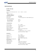
Maintenance Manual SPECIFICATIONS MODEL: PZ-S100 GENERAL Dimensions(Less Antenna) H x W x D Weight Radio (less battery) with battery (2600mAH) Programmable Channels Channel Spacing Power Source Current Drain (maximum) Receive Standby mode Receive Full Audio Transmit at 5 Watts 112.2 × 56mm × 31.9 mm 16 Channels 12.5 / 25 kHz 7.5V DC Rechargeable Li-ion 2600 mAH battery pack 69 mA 350 mA 1.
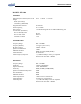
Maintenance Manual MODEL: PZ-S400 GENERAL Dimensions(Less Antenna) H x W x D Weight Radio (less battery) with battery (2600mAH) Programmable Channels Channel Spacing Power Source Current Drain (maximum) Receive Standby mode Receive Full Audio Transmit at 5 Watts 112.2 × 56mm × 31.9 mm 16 Channels 12.5 / 25 kHz 7.5V DC Rechargeable Li-ion 2600 mAH battery pack 69 mA 350 mA 1.
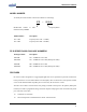
Maintenance Manual MODEL NUMBER To identify the model number of PZ-S series Radio is as followings P Z – S1 0 0 Identification number of radio Frequency Band manufactured by UNIMO Model Number Description PZ – S100 PZ – S400 Frequency band: 136 – 174 Mhz, Frequency band: 400 – 470 Mhz, PZ-S SERIES RADIO PACKAGE NUMBERS Package Number Description PZS10XE PZS10WE 136 – 174Mhz PZ series radio 136 – 174Mhz PZ series radio (Waterproof model) PZS40XE PZS40WE 400 – 470Mhz PZ series radio 400 – 470
Maintenance Manual Scramble function of frequency Inverter Type Compander function Dual Tone Modulation Frequency (DTMF) Selectable Channel Spacing (12.
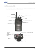
Maintenance Manual CONTROLS & INDICATORS The following section provides a description of the controls and Indicators for the PZ-S series radio. Detailed operating instructions can be found the later chapter.
Maintenance Manual Controls On/Off Volume Switch Turn the knob of Volume Switch clockwise to turn the Radio on and if turning the Switch to the opposite direction, the Radio is turned off. The audio volume level can be adjusted by turning the Volume Switch and when adjusting the volume, please refer to the index mark indicated nearby the Volume knob. The knob of volume doesn’t exist for the GPS model of PZ-S series radio. In this case, press and hold the “F4” button then the radio is turn ON.
Maintenance Manual When this button is assigned to “Emergency” then the red button is activated for emergency function. Press the “Emergency” button in an emergency situation, an emergency siren sound will be heard through the speaker in the Radio. And the Radio will transmit an emergency signal to the party through the emergency channel. Side Button (Scan Button) This button can be pre-assigned for several kinds of function.
Maintenance Manual BATTERY PACKS The following battery pack is available for use with the PZ-S series radio. PBX-2260LA: Rechargeable Battery Packs (2600mAH Li-ion). PBX-2220LA: Rechargeable Battery Packs (2200mAH Li-ion). The PZ-S series Radio receives power from high-performance Li-ion battery. The battery is safe, of high-performance and highly reliable. Using the enclosed standard charger makes it possible to get sufficient efficiency and lifetime of the battery.
Maintenance Manual Installing the Battery Pack Ensure the ON/OFF volume switch is set to OFF position of the radio. Hold the radio and battery pack with the back of them facing you. See Figure Align the hook back of the radio with the hook front side of the battery pack Press and slide the battery pack fully upper side of the radio until the battery release latch click into place.
Maintenance Manual Removing the Battery Pack Ensure the ON/OFF volume switch is set to OFF position of the radio. Press down the release latch and slide the battery pack down side of the radio.
Maintenance Manual Charging the Battery Pack New batteries or batteries that have been stored for a long time period should be fully charged before placing into service. Low battery voltage will shorten the talk range and will make the performance of radio worse. When the battery pack requires charging then the radio will sound a high pitch tone every second How to Charging Plug the charger (CHZ-260FB) into the electricity power outlet for AC220V. The charger (CHZ-260FB) has two slots.
Maintenance Manual When charging the battery only, insert battery into rear slot of the charger. Although the green LED is on after full charge, please continue the charging for 30 more minutes for the complete full charge. During the charging After complete charging Error condition During maintaining charge ☞ CAUTION red LED is turn ON green LED is turn ON red LED is blinks green LED is turn ON Charger used with battery packs must be supplied by UNIMO Technology Co., Ltd.
Maintenance Manual RADIO OPERATIONS Installation and Removal of Antenna Put the antenna into the antenna connector of the radio and turn the antenna clockwise for installation of antenna and in order to remove the antenna from Radio, turn the antenna counterclockwise. ☞ CAUTION` When installation of the antenna, giving a strong pressure to the Radio or pulling the antenna from Radio with a strong power can make damage on the antenna connector, which may cause the Radio to have critical problem.
Maintenance Manual tone or 5 Tone. If frequency is same as current channel but sub-tone is not same as current setting than the green LED blinks. In order to check if the current channel is in use, press the Monitor button (M) on the left side of Radio. If pressing the Monitor button (M) for about 2 seconds, the monitor function is activated with a “beep” sound. To release from the monitor function, press the monitor button shortly. Changing Channels Channel Switch is used for changing channels.
Maintenance Manual Priority Scan As soon as priority scan channel is detected, the radio will change priority scan mode. When the scan channel list is NS1, NS2, NS3 and priority scan channel is PS, the radio proceeds to scan in the sequence of PS, NS1, PS, NS2, PS, NS3, PS, NS1.... During receiving signal through common channel, the radio scans the priority channel periodically. And if the radio detects the signal on the priority channel, it starts to receive the signal from the priority channel.
Maintenance Manual Subtone The radio can be programmed for CTCSS encode/decode tone frequencies and DCS code. CTCSS tone frequency A list of standard tone frequencies for CTCSS tone are describing as shown below. No. Frequency No. Frequency No. Frequency No. Frequency 1 67.0 15 110.9 29 179.9 43 196.6 2 71.9 16 114.8 30 186.2 44 199.5 3 74.4 17 118.8 31 192.8 45 206.5 4 77.0 18 123.0 32 203.5 46 229.1 5 79.7 19 127.3 33 210.7 47 254.1 6 82.5 20 131.
Maintenance Manual DCS code A list of standard DCS tone codes are described as shown below. No. DCS Code No. DCS Code No. DCS Code No.
Maintenance Manual 2 Tone Function The radio encodes the received 2 Tone before receiving the transmission voice when current channel is activated 2 Tone. If the 2 Tone corresponds with that of current channel then radio receives the corresponding 2 Tone normally. (In case of No Tone or the corresponding Sub-tone) VOX The VOX function is set up by Pc-Programmer and without pressing the PTT key, the voice signal is transmitted through microphone.
Maintenance Manual with ”beep” sound. BCL/BCLO BCL/BCLO function is used not to interrupt the other users who are using the same frequency. If BCL/BCLO is activated then transmitting is prohibited from the same channel that was used for others. In this case, alert sound is heard. BCL(Busy Channel Lock) : Prohibit transmission from the same frequency. BCLO(Busy Channel Lock Override) : Prohibit transmission in case of different sub-tone.
Maintenance Manual Squelch Level The user can be set the 9 different squelch levels on the radio. It can be changed on the PC programmer or press the pre-assigned button. Cloning The personality data of radio such as frequency/Tone/Scan can be copied to other radio directly using by cloning function. The following section provides a description of 2 different kind of cloning function. Wire Cloning Prepare the cloning cable (PECLONA) for PZ-S series radio.
Acknowledging Special Precautions and the FCC Notice Cautions. Modifications not expressly approved by the party responsible for compliance could void the user's authority to operate the equipment. FCC compliance Information This device complies with part 15 of FCC Rules. Operation is subject to the following two conditions: 1. This device may not cause harmful interference, and 2. This device must accept any interference received. Including interference that may cause undesired operation.
RADIO FREQUENCY ENERGY SAFETY INFORMATION This UNIMO transceiver has been tested and complies with the standards listed below, in regards to radio Frequency(RF) energy electromagnetic energy(EME) generated by the transceiver > FCC RF exposure limits for Occupational use only. RF exposure limits adopted by the FCC are generally based on recommendations from the national council on radiation protection and measurement, & the American National National Standards Institute.
> Do not transmit for more than 50% of the total transceiver use time; transmitting over 50% of the total use time may exceed the limits in accordance to the FCC RF exposure requirements. Nominal transceiver operation is 5% transmission time,5% reception time, and 90% stand-by time > Use only the specified antenna for this transceiver; this may be either the antenna provided with the transceiver or another antenna authorized by UNIMO.
IMPORTANT Safety Instruction: 1) Read these instructions. 2) Keep these instructions. 3) Heed all warnings. 4) Follow all instructions. 5) Do not use this equipment near water. 6) Do not using near any heat sources such as radiators, heat resisters, stove, or other equipment that produce heat.
European Union Regulatory Notice Compliance with these directives implies conformity to harmonized European standards (European Norms) that are listed in the EU Declaration of Conformity issued by HP for this product or product family. This compliance is indicated by the following conformity marking placed on the product.