User Manual MINIpower PLUS Pioneering solutions for total power protection
Document Control ISSUE DATE REVISION SUMMARY Draft A 7-11-11 First draft issued for comments Draft A1 9-2-12 Second draft incorporating rack-mounted model Issue 1.
Uninterruptible Power Supplies Ltd has taken every precaution to produce an accurate, complete and easy to understand manual and will therefore assume no responsibility nor liability for direct, indirect or accidental personal or material damage due to any misinterpretation of or accidental mistakes in this manual. © 2005 Uninterruptible Power Supplies Ltd This manual may not be copied nor reproduced without written permission of Uninterruptible Power Supplies Ltd.
: 1 Safety 1.1 Description of symbols used in this manual 1.2 User precautions 2 General Description 2.1 2.2 2.3 2.4 2.5 2.6 3 Reliability and Quality Standards MINIpowerPLUS Model Range Operating Principles Warranty Extended Warranty Additional Service/Maintenance Support 6-1 6-1 6-2 6-3 6-3 6-4 6-4 6-5 6-5 6-6 6-7 6-10 6-11 6-12 6-12 Maintenance 5.1 Introduction 5.2 Routine maintenance 5.3 Battery Testing 6 5-1 5-1 5-2 5-2 5-2 5-2 5-3 5-3 5-4 5-4 5-5 5-5 5-7 5-8 5-11 Operation 4.
: 7 Options 7.1 Maintenance Bypass 7.1.1 Introduction 7.1.2 Installation 7.1.3 Functional testing 7.1.4 Maintenance bypass specification 7.2 Shutdown and Monitoring Software 7.2.1 Introduction 7.2.2 WAVEMON UPS monitoring software 7.2.3 SNMP ADAPTER for network management/remote monitoring 7.3 PowerREPORTER™ management software 7.3.1 Relay Interface Board 8 Specifications 8.1 Construction Features 8.2 Environmental 8.3 Electrical Input 8.4 Output Waveform 8.5 Output When Running on Mains Power 8.
1 1.1 Safety Description of symbols used in this manual WARNING: The warning symbol is used where there is danger of an electrical shock, equipment damage or personal-injury. CAUTION: The caution symbol is used to highlight important information to avoid possible equipment malfunction or damage. 1.2 User precautions WARNING: Keep this manual with the UPS for future reference.
1: Safety 1-2 UPS453-01-00 MINIpowerPLUS User Manual Dated 08-03-12
2 2.1 General Description Reliability and Quality Standards Congratulations on your purchase of the MINIpowerPLUS UPS. The MINIpowerPLUS UPS incorporates the latest technological advances in power engineering to offer a highly reliable, upgradeable UPS system with excellent electrical performance and low running costs. Uninterruptible Power Supplies Ltd.
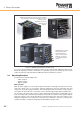
2: General Description MINIpowerPLUS 5000 (Rack and Tower) cabinets Fully populated with 4 Power Modules to offer a 5.0kVA system. Batteries are housed within the UPS cabinets. MINIpowerPLUS 10000 Fully populated with 8 Power Modules to offer a 10kVA system. Batteries are housed in a matching battery cabinet. Figure 2.
2: General Description Bypass Line INP UT O UT P UT ~ POWER FACTOR CORRECTION OUTPUT FILTER ~ = INPUT FILTER STATIC SWITCH = INVERTER POWER MODULE = = BATTERIES VOLTAGE BOOSTER BATTERIES BATTERY CHARGER POWER MODULE POWER MODULE BATTERIES M I C RO PR O C ESSO R LO G I C R EMO T E CO NT RO L RS232 I NT ER F ACE Figure 2.
2: General Description The voltage booster stage obtains its power from the batteries, and when the UPS operates in this mode the operator is informed that the battery is ‘on load’ and therefore discharging, and a number of alarms activate at preset voltage levels as the battery discharges. The operating threshold and function of these battery alarms can be set by the operator through the UPS Setup menu to suit local application requirements.
2: General Description 2.5 Extended Warranty The Standard Warranty may be enhanced by protecting the UPS with an Extended Warranty Agreement (maintenance contract). An Extended Warranty Agreement enhances the standard warranty by providing the following: • • • • Regular preventative maintenance inspections Guaranteed speed of response to operational problems 24 hour telephone support Fully comprehensive (excluding batteries) cover Contact the Service Support Hotline on 0800 731 3269 for further details.
2: General Description www.upspower.co.uk Fax to: 0118 981 5152 Uninterruptible Power Supplies Ltd. Bacchus House Calleva Park Aldermaston Berkshire RG7 8EN Tel: 0118 981 5151 Name: ............................................................................................ Job Title: ............................................................................................ Company: ............................................................................................ Address: ..........
3 3.1 Installation Introduction This chapter contains all the information necessary to enable you to correctly install the MINIpowerPLUS UPS, including unpacking, storage, positioning and cabling instructions. WARNING: The electrical installation of this UPS system and its peripheral equipment must be carried out by an authorised electrician or other suitably qualified personnel. Uninterruptible Power Supplies Ltd.
3: Installation 3.1.2 Site transportation When locally transporting the UPS equipment after it has been off loaded please observe the following cautions: CAUTION: If dropped, the weight of the UPS cabinet could cause serious injury to personnel or damage equipment in the surrounding area. Always handle with care. If the equipment is accidentally dropped do not connect it to the mains electricity supply. 3.1.
3: Installation period they should be recharged periodically to prevent them from losing their original capacity. As a guide, the batteries should not be stored for longer than the periods shown below without being recharged: • 6 months at 20°C • 3 months at 30°C • 2 months at 35°C CAUTION: Sealed batteries must never be stored in a discharged or partially discharged state. The batteries can be destroyed by extreme temperature, under-charge, overcharge or over-discharge! 3.
3: Installation 3.2.2 MINIpowerPLUS Rack-mounted versions Rack positioning and accessibility The MINIpowerPLUS Rack-mounted UPS cabinet is designed to fit into a standard 19 inch rack and is 6U high. The cabinet is fitted through the front of the rack, supported on suitable rails and secured in position by means of two screws on each side of the front of the assembly.
3: Installation 3.3 UPS Installation Procedure 1 2 3 3 2 1 1. External battery connections 2. Communications interface connections 3. UPS Input/Output power receptacle Note that the Rack-mounted rear panel is identical to the Tower version but turned on its side. Figure 3.3 MINIpowerPLUS 5000 Electrical connections The UPS is installed in three stages: 1.
3: Installation MINIpowerPLUS 10000 installation Note: Applies to models 5000/2, 6250/2, 7500/2, 8750/2 & 10000/2. Battery Connectors Chassis Earth Stud UPS Cabinet Braided Earth Strap Battery Cabinet Figure 3.4 MINIpowerPLUS 10000 battery connections 1. Connect the flexible braided earth strap (provided) between the chassis earth studs of both cabinets – the studs are located adjacent to the battery connectors. 2. Connect all three battery cables between the battery connectors on both cabinets.
3: Installation Extended battery cabinet connections Additional battery cabinets can be connected to either of the above systems to further extend the available autonomy time. A A Standard cable Where an extended cabinet is used, the standard cabinet inter-connect cables are replaced by ‘splitter’ cables that can be effectively daisy chained to connect any number of cabinets together – as illustrated in Figure 3.6.
3: Installation 3.3.3 Connect the UPS input/output power cables The UPS input and output cables are fitted to a single power connector that plugs into a receptacle located on the rear UPS cabinet wall. A ready-made connector complete with cable is provided with the equipment. The supplied cable is approximately 600mm in length and terminated with an input plug and outlet socket suitable for the UPS capacity rating.
3: Installation MINIpowerPLUS 5000 power connector wiring CAUTION: Ensure the UPS input mains supply is isolated before proceeding. Never remove the 230 V power plug whilst the UPS is in operation as this would disconnect the earth protection of both the UPS and of the connected loads. Figure 3.
3: Installation MINIpowerPLUS 10000 power connector wiring CAUTION: Ensure the UPS input mains supply is isolated before proceeding. Never remove the 230 V power plug whilst the UPS is in operation as this would disconnect the earth protection of both the UPS and of the connected loads.
3: Installation 3.3.4 Powering ON the UPS WARNING: If the batteries are not already fitted and connected: • Do not continue beyond this point in the installation procedure. The equipment must be commissioned by a manufacturer-approved engineer. • Do not turn on the input mains power until the equipment has been commissioned.
3: Installation 3-12 UPS453-01-00 MINIpowerPLUS User Manual Dated 08-03-12
4 4.1 Operation Operating Instructions Two sets of Operating Instructions are provided below; the first applies to a standard installation and the second applies if the Maintenance Bypass option is fitted. Note: If the Maintenance Bypass option is fitted there will be a BYPASS switch on the mains power connector plugged into the back of the UPS.
4: Operation 4.1.2 Installation with Maintenance Bypass option fitted To switch ON the UPS (assuming the maintenance bypass switch is closed) 1. On the UPS Control Panel press the ON/OFF button once. a) The Control Panel LCD display will initially show UPS Switching on... b) As the UPS runs through its start-up checks the Control Panel status indicator will change from red to yellow and then finally remain green.
4: Operation 4.2 Control Panel The UPS is fully controlled from the operator control panel located on the front of the UPS. The user-friendly control panel comprises three areas: Alpha-numeric LCD Display Normally provides indication of the UPS operating mode together with the input/ output supply parameters and the battery ‘state of charge’ (SOC).
4: Operation 4.2.2 Operator Keypad ‘ ESCape Key • Exit a function without modifying it • Go up one menu level • Exit the main menu and return to the status display • Silence the buzzer SCROLL UP Key • Select previous function • Increase a value • Select a new item within the function (e.g. go from DISABLED to ENABLED) SCROLL DOWN Key • Select next function • Reduce a value • Select a new item within the function (e.g.
4: Operation 4.4 UPS Customisation and Event Monitoring Menus The UPS control system can be monitored and customised through a series of menus that can be displayed on the LCD panel and accessed using the operator keypad buttons. This facility is used by the service engineer to set-up the UPS during commissioning and to monitor the UPS performance and alarms history when undertaking maintenance or troubleshooting.
4: Operation 4.4.2 UPS Status Menu The UPS Status menus are provide the user with information concerning the UPS set-up configuration and operational data – both live and historical. Most of the sub-menus are self-explanatory, as shown below. UPS Info sub-menu MAIN MENU UPS Status UPS Setup Events Scheduling Tools UPS STATUS UPS Info Output Input Batteries History Data Misc.
4: Operation Misc. sub-menu MAIN MENU UPS STATUS UPS Status UPS Setup Events Scheduling Tools UPS Info Output Input Batteries History Data Misc. MISC. Int. Temp Ext. Temp Fan Speed xx xx xx UPS Internal termperature (deg C.) UPS External termperature (deg C.) Percentage fan speed (max 100) 4.4.3 UPS Setup Menu The UPS Setup menu is used to set-up various UPS operating parameters and functions.
4: Operation Bypass sub-menu MAIN MENU UPS Status UPS Setup Events Scheduling Tools UPS SETUP Output Input Bypass Neutral Sensor Batteries Clock Setup Operator Panel BYPASS Bypass Enable Forced mode DIP Speed Off-line mode Load Wait mode Enable/Disable bypass intervention Enables permanent bypass operation Sets bypass intervention sensitivity Selects Off-line mode of operation Selects operate on bypass on low load Bypass Enable: If enabled, the UPS manages bypass operation automatically.
4: Operation Batteries sub-menu MAIN MENU UPS Status UPS Setup Events Scheduling Tools UPS SETUP Output Input Bypass Neutral Sensor Batteries Clock Setup Operator Panel BATTERIES Capacity Manage Reserve Time Max Time on Batt Max Time Reserve Turn On Test Enable Restart Enable External Options Determines autonomy calculation method Set reserve operating time Set max operating time on battery Set operating time after reserve is reached Enable battery test when UPS is turned on Auto restart when mains retu
4: Operation Clock Setup sub-menu MAIN MENU UPS Status UPS Setup Events Scheduling Tools UPS SETUP Output Input Bypass Neutral Sensor Batteries Clock Setup Operator Panel BATTERIES Capacity Manage Determines autonomy calculation method Operator Panel sub-menu MAIN MENU UPS Status UPS Setup Events Scheduling Tools UPS SETUP Output Input Bypass Neutral Sensor Batteries Clock Setup Operator Panel OPERATOR PANEL Language Keyboard Beep Display Backlight Display Contrast Password Change Selects the operat
4: Operation 4.4.5 Scheduling Menu Schedule Planning sub-menu MAIN MENU UPS Status UPS Setup Events Scheduling Tools SCHEDULING Schedule Planning Restart Shutdown Planning SCHED. PLANNING Enable View/Edit Sched. Sequence Reset Enable/Disable set programmes Set and modify program schedule Displays set programmes in daily order Delete all settings The Schedule Planning sub-menu allows various operating functions to be set to be programmed to operate at predetermined times.
4: Operation 4.4.6 Tools Menu MAIN MENU UPS Status UPS Setup Events Scheduling Tools TOOLS Signalling Test LCD Display Test Battery Test Battery Calibration ENTER to activate test of Red/Yellow/Green lights and audible sounder. ENTER to activate test. All alpha/numeric characters should display on LCD ENTER performs a functional check of the batteries.
5 5.1 Maintenance Introduction WARNING: All the maintenance operations described in this chapter must be performed by an authorised electrician or other suitably qualified personnel. As the UPS contains no user-serviceable parts, the maintenance requirements to be carried out by the user are minimal beyond ensuring that the UPS operating environment remains suitably cool and dust-free. 5.
5: Maintenance 5-2 UPS453-01-00 MINIpowerPLUS User Manual Dated 08-03-12
6 6.1 Troubleshooting Potential Problems and Solutions Problem Possible Solution When the UPS is switched on, the buzzer sounds and the red warning light makes alternating short-long flashes, then the UPS switches off after 15 seconds. The connection of the neutral conductor is incorrect: • Swap the connections of the neutral and phase input leads, or exclude the neutral sensor. The UPS works but a short beep is heard every 12 seconds and the yellow warning light is lit without flashing.
6: Troubleshooting 6-2 UPS453-01-00 MINIpowerPLUS User Manual Dated 08-03-12
7 7.1 Options Maintenance Bypass 7.1.1 Introduction INPUT MAINS LOAD SUPPLY Bypass Relay PE N L PE N L Fuse N/O UPS Output Relay N/C Maintenance Bypass Switch UPS Figure 7.1 Maintenance bypass circuit The Maintenance Bypass option allows the load to be transferred to the raw input mains supply if it is necessary to completely shut down or remove the UPS for maintenance or repair purposes.
7: Options Both relays and the maintenance bypass switch are built in to the UPS power connector (which replaces the standard power connector). The switch contains a yellow lamp which illuminates when the switch is closed to indicate that the load is connected to the maintenance bypass, as shown below in Figure 7.2. MINIpowerPLUS 5000 MINIpowerPLUS 10000 Figure 7.2 Maintenance bypass switch location 7.1.
7: Options Live Live Neutral Neutral PE PE Mains input cable UPS output cable Figure 7.3 Maintenance bypass connector (MINIpowerPLUS 5000) Live Neutral Neutral Live PE PE UPS output cable Mains input cable Figure 7.4 Maintenance bypass connector (MINIpowerPLUS 10000) 7.1.3 Functional testing 1. Connect the input cable to the mains power supply and connect a load to the UPS output (e.g. a lamp). 2. Turn ON the UPS input mains power. 3.
7: Options 7.1.4 Maintenance bypass specification MINIpowerPLUS 5000 MINIpowerPLUS 10000 Input voltage 184V - 265V 184V - 265V Output voltage 184V - 265V 184V - 265V Input/Output Current 23A max 46A max Maximum UPS power 5kVA 10kVA 25A FF 2x32A FF Input line fuse Protection Dimensions (w x h x d) 7.2 IP20 IP20 240 x 145 x 59 224 x 250 x 55 Shutdown and Monitoring Software 7.2.
7: Options Figure 7.5 WAVEMON Monitoring screen image WAVEMON Operation The UPS-Management software is a client/server-application for networks and local workstations and consists of two parts: the server-module of the UPS-Management Software is called UPSServ and the clientmodule UPSCli.
7: Options 7.2.3 SNMP ADAPTER for network management/remote monitoring Simple Network Management Protocol (SNMP) is a world-wide standardised communication protocol that can be used to monitor any network-connected device via a simple control language. The monitored results are displayed in a web browser. When this facility is used in conjunction with the MINIpowerPLUS, an external SNMP adapter is used which is connected to the RS232 connector on the UPS back panel.
7: Options 7.3 PowerREPORTER™ management software PowerREPORTER™ is a remote monitoring and management service which is a part of the premium power protection concept. ThePowerREPORTER™ application: • Provides affordable, continuous monitoring over mission-critical facilities and offers peace-of-mind by detecting and warning of any potential system problems before they become a crisis.
7: Options 7.3.1 Relay Interface Board The Relay Interface Board provides volt-free alarm and status outputs that can be connected to a remote panel. The board is contained in an ABS box which is fitted to the UPS back panel and connected to the 9-pin D-type connector on the back of the UPS by means of the supplied 0.6m ribbon cable. The box cover is held in place by moulded clips and can be easily removed to provide access to the output terminal connectors.
8 8.1 Specifications Construction Features UPS Model Range Weight UPS Cabinet (Kg.) MINIpowerPLUS 5000 MINIpowerPLUS 10000 1250 2500 3750 5000 5000/2 6250/2 7500/2 8750/2 10000/2 23.5 34 43 53 24+50 26.5 29 31.5 34 50 57.5 65 72.5 380 Weight Battery Cabinet (Kg.) Size (mm) (WxDxH) Tower: 270 x 475 x 570 19" Rack: 483.5 x 266 x 600 (6U) 270 x 475 x 570 x 2 cabinets Technology PWM high frequency both for input stage and output stage. Microprocessor control logic.
8: Specifications 8.3 Electrical Input UPS Model Range MINIpowerPLUS 5000 1250 2500 3750 MINIpowerPLUS 10000 5000 Nominal Input Voltage 6250/2 7500/2 8750/2 10000/2 230V Input Voltage Range 184V to 264V with nominal load 100V to 264V with 50% nominal load Frequency 50 or 60Hz ± 2% auto-sensing and/or selected by operator Current (Nom.) 4.6A 8.9A 13.2A 17.7A 17.7A 22.4A 26.9A 31.25A 36.6A Current (Max.) 5.75A 11.2A 16.6A 22.2A 22.2A 27.8A 33.25A 38.9A 44.
8: Specifications 8.6 Output When Running on Battery Power UPS Model Range MINIpowerPLUS 5000 1250 2500 3750 MINIpowerPLUS 10000 5000 Nominal Output Voltage 5000/2 6250/2 7500/2 8750/2 10000/2 230 V ± 1% Nominal Output frequency 50 Hz / 60Hz synchronised (auto-sensing and/or as selected by operator) Output VA 1250 2500 3750 5000 5000 6250 7500 8750 10000 Output W with 0.
8: Specifications 8.