INSTALLATION & OPERATING MANUAL X100 SERIES DC POWER POWER SYSTEM www.unipowerco.com Manual No. X100-5a x100-man-Rev5a-0214.indd © 2014 UNIPOWER LLC All Rights Reserved NORTH AMERICA • 3900 Coral Ridge Drive, Coral Springs, Florida 33065, USA • Tel: +1 954-346-2442 • Fax: +1 954-340-7901 • sales-northamerica@unipoweco.com EUROPE • Parkland Business Centre, Chartwell Road, Lancing BN15 8UE, ENGLAND • Tel: +44(0)1903 768200 • Fax: +44(0)1903 764540 • sales-europe@unipoweco.
X100 SERIES INSTALLATION & OPERATING MANUAL CONTENTS 1.0 INTRODUCTION..................................................................................................................4 2.0 FEATURES & OPTIONS.......................................................................................................5 3.0 SAFETY WARNINGS...........................................................................................................5 4.0 WARRANTY (summary).................................................
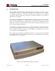
X100 SERIES INSTALLATION & OPERATING MANUAL FIGURES Figure 1 Figure 2 Figure 3a Figure 3b Figure 4 Figure 5 Figure 6 Figure 7 Figure 8 Figure 9 Figure 10 Figure 11 Figure 12 Figure 13 Figure 14 Figure 15 Figure 16 X100 Compact Integrated DC Power System................................................................4 Front Panels with Bezel Removed..................................................................................9 Rear Panel – Options A & B..................................................
X100 SERIES INSTALLATION & OPERATING MANUAL 1.0 INTRODUCTION Gravitas X100 is an ultra-compact, integrated, DC power system. It consists of up to three high power-density, hot-swap rectifier modules which can produce up to 66 amperes at -54.4VDC, 99 amperes at +27.2VDC or 100 amperes at +13.6VDC. In 2+1 redundant operation the output current is up to 44 amperes at -54.4VDC, 66 amperes at +27.2VDC or 100 amperes at +13.6VDC.
X100 SERIES INSTALLATION & OPERATING MANUAL 2.0 FEATURES & OPTIONS 2.1 Standard Features 2.2 Options & Accessories 3.0 2RU High System Unit Remote Control & Monitoring via TPC/IP Ethernet LAN Fully Integrated System Up to 66A at -54.4VDC Up to 99A at +27.2VDC Up to 100A at +13.
X100 SERIES INSTALLATION & OPERATING MANUAL 4.0 WARRANTY (summary) X100 Series DC power systems are warranted for two (2) years from date of shipment against defects in material and workmanship.
X100 SERIES INSTALLATION & OPERATING MANUAL 6.0 GENERAL SPECIFICATIONS 6.1 Inputs Supply Voltage: 85-264VAC Single Phase Each rectifier position is supplied via an individual pair of screw terminals. A 3-phase supply may be connected provided that the voltage presented to each individual rectifier position does not exceed 264VAC. Supply Current: Max 17A input @ 85-264VAC per rectifier input. Battery Input: Direct connection to DC output bus or via protection breakers.
X100 SERIES INSTALLATION & OPERATING MANUAL 6.4 Safety The X100 system is compliant with UL60950-1, EN60950-1, CSA22.2-60950-1 and all other derivatives of the core IEC60950-1 standard 2nd Edition when installed correctly within a restricted access environment. The X100 system is CE marked to indicate conformance to the European Union’s Low Voltage and EMC Directives. 6.5 EMC The X100 complies with the following Norms when correctly installed. 6.6 6.
X100 SERIES INSTALLATION & OPERATING MANUAL 7.0 FRONT PANEL DESCRIPTION OPTION A – MINIATURE CIRCUIT BREAKERS BATTERY BREAKERS DC DISTRIBUTION 1-8 CIRCUIT BREAKERS LOAD CURRENT DISPLAY 16 LED STATUS & ALARM MATRIX HOT-SWAP RECTIFIER MODULES OPTION B – GMT FUSES DC DISTRIBUTION 10 GMT FUSES OPTION C – BULK FEED CIRCUIT BREAKERS DC DISTRIBUTION 1-4 CIRCUIT BREAKERS Figure 2 - Front Panels with Bezel Removed 7.1 From left to right there are 3 rectifier slots.
X100 SERIES INSTALLATION & OPERATING MANUAL 7.2.3 7.3 8.0 Option C provides up to 4 bulk DC load circuits with circuit breaker protection. Each circuit may be specified with a breaker of maximum rating 50A. To the right of the DC distribution section is a display section. 7.3.1 Current Meter – displays the total system load current. 7.3.2 16 LED Matrix – provides visual indication of a variety of status and alarm condition. Full details can be found in section 9.
X100 SERIES INSTALLATION & OPERATING MANUAL 8.2 8.3 To the right are two pairs of terminal blocks for making connections to one or two strings of batteries. Batteries are connected to the internal system bus via two magnetic circuit breakers on the front of the unit, each rated at 100A. These circuit breaker provides two functions. 8.2.1 In the first instance they enable the user to disconnect the batteries from the system for maintenance, replacement or other purposed. 8.2.
X100 SERIES INSTALLATION & OPERATING MANUAL 9.0 CURRENT METER & LED INDICATORS Figure 4 - Current Meter and LED Indicators (showing MAJ & FUSE alarms) During normal operation only the green PWR LED is displayed along with an reading of the load current. The LED indicators provide visual indication of both status and alarm conditions as described below: PWR – GREEN – Indicates that the unit has power. FLT – GREEN – Indicates that the unit is in ‘Float’ mode.
X100 SERIES INSTALLATION & OPERATING MANUAL 10.0 MAKING CONNECTIONS TO THE X100 10.1 DC Load Connections The DC load distribution connections at the rear left of the unit are clearly marked as follows: 10.1.1 Option A – 1-8 miniature circuit breaker. Terminals marked 1-8 are used for breakers marked 1-8 respectively. Each circuit has a FEED and a RETURN (RTN) connection. Terminals marked 9 and 10 are not used. 10.1.2 Option B - GMT Fuses. Terminals marked 1-10 are used for fuse marked 1-10 respectively.
X100 SERIES INSTALLATION & OPERATING MANUAL 10.2 Battery Connections The X100 can be connected to two separate battery strings through the battery two pairs of IMO ER35 terminal blocks. These terminals accept cables in the range 10AWG to 2AWG. A minimum cable size of 4AWG is recommended when employing only the internal 100A circuit breakers for protection (see section 8.2).
X100 SERIES INSTALLATION & OPERATING MANUAL 10.4 Ethernet Connection – J1 The X100 is connected to a TCP/IP LAN (Local Area Network) or directly to a PC using connector J1. This is a standard RJ45 network connector allowing connection of any generally available Ethernet cable. Note that if the X100 is to be connected directly to a PC rather than a LAN then a cross-over Ethernet cable will be required.
X100 SERIES INSTALLATION & OPERATING MANUAL 11.0 INSTALLATION The X100 can be mounted in either 19” or 23” racks by using the supplied brackets. Mount it from the front of the rack using the correct offsets to align with existing rack-mounted equipment. Once mounted in the rack the following connections must be made with the unit switched off. CAUTION: Re-read the Safety Warnings and Precautions in Section 3. All power should be OFF for the input and output loads before making connections.
X100 SERIES INSTALLATION & OPERATING MANUAL One by one, turn each output circuit breaker to the ON position and/or insert a GMT fuse and measure the DC voltage across the corresponding output terminals. The voltage should again read approximately 54.4, 27.2, or 13.6 volts. After each output is measured, turn OFF that circuit breaker and/or remove the GMT fuse and turn ON and/or insert a fuse in the next one.
X100 SERIES INSTALLATION & OPERATING MANUAL With AC input unplugged, remove the three rectifier modules from the system chassis. Make sure all load circuit breakers are in the OFF position and/or all GMT fuses removed. Set the battery circuit breaker to the OFF position. Carefully connect the battery cables to the battery terminals shown in Figure 4 while observing the correct polarity as described in section 8.4.
X100 SERIES INSTALLATION & OPERATING MANUAL IMPORTANT NOTES: a) It is not possible to start the system by connecting the batteries alone. b) During the 30 seconds initialization period the system bus voltage will be at the factory preset level of the rectifiers; nominally 54.4V, 27.2V or 13.6V depending on system voltage. After this period the internal controller will lower the output voltage by approximately 15% in order to limit current flowing to the batteries.
X100 SERIES INSTALLATION & OPERATING MANUAL 12.0 USING THE CONTROLLER WEB BROWSER INTERFACE The X100 controller is provided with a built-in WEB server which can be accessed through the TCP/IP Ethernet port using a WEB browser. The WEB server employs Java Applets to continually scan system parameters and update the WEB page data. These same Applets return programming data to the DSC1000 when set-up changes need to be made.
X100 SERIES INSTALLATION & OPERATING MANUAL Ensure that ‘Enable Java content in the browser’ is checked and leave the “Security Level” set to “High (minimum recommended)” Click on the Manage Site List button and the following will appear. Click the Add button and type in the IP address of the controller in the format ‘http://xxx.xxx.xxx.xxx’ (substitute the IP address set in the controller). A warning will appear indicating that this is a security risk. Press Continue to allow the site to be added.
X100 SERIES INSTALLATION & OPERATING MANUAL is closed and re-opened. The controller has various network programming capabilities which allow it to be connected to almost any configuration of IP network. The default network settings that the controller is shipped with are: IP Address – 192.168.000.200 Subnet Mask – 255.255.255.000 Gateway – 000.000.000.
X100 SERIES INSTALLATION & OPERATING MANUAL IMPORTANT NOTE: The screen shots shown throughout this section are ‘typical’ examples. The exact data content will differ dependent on the system voltage and whether alterations from the default settings have been made. Settings can be returned to the factory defaults at any time by clicking on the ‘DEFAULT’ then ‘UPLOAD’ buttons on the relevant setup page. This action requires the level 1 pass code.
X100 SERIES INSTALLATION & OPERATING MANUAL 12.1 Controller Status When the X100 is first accessed using a WEB browser the Controller Status page shown below is downloaded. Figure 5 - Controller Status WEB Page (typical) This page presents two blocks of information. The top block displays a number of system status parameters by mimicking a block of LEDs. 7 of these functions, described earlier, are displayed on the front panel of the system unit.
X100 SERIES INSTALLATION & OPERATING MANUAL 12.2 Rectifier Status The Rectifier Status page presents detailed information about an individual rectifier module. Two types of data are included; ‘live’ status information and ‘static’ inventory information. In addition the controller returns the I²C address as confirmation that the unit has responded.
X100 SERIES INSTALLATION & OPERATING MANUAL A few seconds after the SELECT button has been pressed the X100 will respond and the status and inventory information will be updated. ‘Live’ data is presented in the form of 8 colored indicator blocks to the left. A green block indicates a ‘good’ condition and a red block indicates a ‘bad’ condition. In addition the unit’s internal temperature is presented on the right.
X100 SERIES INSTALLATION & OPERATING MANUAL 12.3 Controller Factory Calibration The primary purpose of the Controller Factory Calibration page is to allow UNIPOWER to setup a range of necessary calibration values to ensure correct operation. When this page is requested and the Java applet has loaded a dialog requesting the Level 2 Pass code is presented. Once the pass code has been entered click ENTER and the page will then be updated with current values after a few seconds.
X100 SERIES INSTALLATION & OPERATING MANUAL 12.4 Controller Site Installation The Controller Site Installation page provides the system integrator or installer facilities for setting up the main system parameters. Figure 8 - Controller Site Installation WEB Page (typical) To retrieve the currently programmed settings from the X100 click on REFRESH. After a few seconds the values will be displayed. To reprogram to the factory default settings click on DEFAULT.
X100 SERIES INSTALLATION & OPERATING MANUAL SITE DETAILS Site Name – Optional setting which may be used to identify the location of the unit. Serial Number – Displays the unit serial number. (Cannot be changed.) SYSTEM VOLTAGES System – Dial in the Nominal system voltage; 12V, 24V or 48V. Float – Enter the float voltage in accordance with the specifications of the batteries that are being employed with the system.
X100 SERIES INSTALLATION & OPERATING MANUAL TEMPERATURE COMPENSATION Temp Comp (mV/°C/Cell) – Enter the temperature compensation slope value in accordance with the specifications of the batteries that are being employed with the system. Number Of Cells – Enter the total number of battery cells. Max Temp (°C) – Enter the maximum temperature at which temperature compensation may be applied. Above this temperature the X100 will cease to apply further compensation to the float voltage.
X100 SERIES INSTALLATION & OPERATING MANUAL DC WALK-IN ON (Default) – Causes the controller to slowly ramp up the DC rectifier voltage when AC is applied. The voltage will rise from approximately 45V (for 48V systems), 22V (for 24V systems) and 11V (for 12V systems) up to the float voltage. The ramp-up time is several minutes and cannot be adjusted. The purpose of this feature is to avoid initially large battery charging currents.
X100 SERIES INSTALLATION & OPERATING MANUAL 12.5 Alarm Configuration The Alarm Configuration page presents a matrix of tick boxes which are used to programme how certain system conditions affect the actions of the alarm relays and front panel LEDs. It is also used to define the ‘good’ condition (polarity) of the auxiliary digital input. The screen shot below shows the factory default settings. Figure 9 - Alarm Configuration WEB Page (typical) 12.5.
X100 SERIES INSTALLATION & OPERATING MANUAL MIN LED – An item ticked in this column will enable the MINOR alarm LED when active. ACF LED – An item ticked in the column will activate the ACF LED when the condition occurs. RFA LED – An item ticked in the column will activate the RFA LED when the condition occurs. OTA LED – An item ticked in the column will activate the OTA LED when the condition occurs. OVA LED – An item ticked in the column will activate the OVA LED when the condition occurs.
X100 SERIES INSTALLATION & OPERATING MANUAL EMAIL – When the email reporting feature is activated ticking an item in this column results in an email message being sent immediately. 12.5.2 Aux. Input Polarities By selecting the NO or NC radio buttons for the AUX 3 input the ‘good’ condition can be set to either Normally Open or Normally Closed respectively. NOTE THAT THE LVD AND FUSE SETTINGS ARE PRESET AND SHOULD NOT BE CHANGED. AUX 4 to AUX 8 are not fitted on the X100 system.
X100 SERIES INSTALLATION & OPERATING MANUAL 12.6 Comms Clicking on the Comms button loads to Controller Network Settings page. This page is used to setup the Ethernet and E-Mail communications settings. Figure 10 - Controller Network Settings (typical) 12.6.1 Ethernet Settings 12.6.1.1 IP Address This setting defines the IP Address for the controller. The default factory setting of 192.168.0.
X100 SERIES INSTALLATION & OPERATING MANUAL To alter the Subnet mask use the up/down arrows to dial in the required numbers or type them directly into the boxes as required. It is important to press the ENTER key on completion. 12.6.1.3 Default Gateway This setting defines the Network Gateway to which the controller will route all IP traffic that is destined for any location outside the LAN to which it is connected.
X100 SERIES INSTALLATION & OPERATING MANUAL 12.6.2.4 Controller E-Mail The X100 requires an email address of its own to send email alarm messages. Note, however, that it is unable to receive messages sent to this address. Type in the desired address in the Controller E-Mail box using the normal name@domain format and press the ENTER key to confirm. Once all desired Ethernet and E-Mail settings have been entered click on the UPLOAD button to programme them into the controller.
X100 SERIES INSTALLATION & OPERATING MANUAL 12.7 Alarm Log The Alarm Log page can be used to view a history of alarm and other conditions that have occurred. When this page is first loaded the alarm log window will be empty. To load the current log file click on REFRESH. After a few seconds the log data will be loaded. To clear the log click on the CLEAR button, the refresh the page click on the REFRESH button. Figure 11 - Controller Alarm Log WEB Page (typical) Manual No.
X100 SERIES INSTALLATION & OPERATING MANUAL 12.8 Control The Controller Control Panel page is used to remotely switch the system between FLOAT and EQUALIZE modes. This page displays various system status functions enabling the operator to monitor these system parameters from a remote location. To set the system to equalize mode click on the EQUALIZE button. After a few seconds the unit will respond by switching off the FLT LED indicator and switching on the EQU LED indicator.
X100 SERIES INSTALLATION & OPERATING MANUAL 12.9 System The Controller System Settings page enables a user to alter the controller’s real-time clock date and time settings. New date and time settings can be entered manually or automatically synchronized with a ‘host’ system. Figure 13 - Controller System Settings WEB Page (typical) 12.9.1 Manual Setting To enter a new date and/or time manually either use the up/down buttons to dial in the desired settings or type them directly into the required boxes.
X100 SERIES INSTALLATION & OPERATING MANUAL 12.10 SNMP The SNMP Configuration page is used to setup the controller’s SNMP System Information, Alarm Trap and Agent Information parameters. It also allows the SNMP feature to be activated. Figure 14 - SNMP Configuration WEB Page (typical) Note: It is assumed that customers wishing to employ the SNMP features of the X100 will be familiar with the necessary set-up procedure for this page.
X100 SERIES INSTALLATION & OPERATING MANUAL 12.11 Help The Controller Help Page provides a few quick reminder notes. For more detailed help the user is referred to this manual. Figure 15 - Controller Help WEB Page (typical) 12.12 About The About UNIPOWER Telecom page provides contact information in case additional technical or other support is required. Figure 16 - About UNIPOWER Telecom WEB Page (typical) Manual No. x100-5a Page 42 x100-man-Rev5a-0214.
X100 SERIES INSTALLATION & OPERATING MANUAL Appendix 1 – SNMP MIB Information The SNMP feature provides status read-out and alarm trapping only. All parameters described in this appendix are therefore read-only. Refer to the appropriate sections earlier in the main body of this manual for system set-up. Parameters for UNIPOWER X100 Remote Access Controller MIB 1. Voltages Bus Voltage - Description: Live data giving actual voltage of system bus. 2.
X100 SERIES INSTALLATION & OPERATING MANUAL 6. Alarms These are all part of one alarm status flag held within the controller. ACFAIL - Indicates an AC Failure detected by the power supply rectifiers or an external sensor. MAJOR - Indicates that a major alarm condition requiring immediate attention has been detected by the controller. MINOR - Indicates that a minor alarm condition requiring attention at the next scheduled maintenance has been detected by the controller.
X100 SERIES INSTALLATION & OPERATING MANUAL 7. Settings OVER VOLTAGE ALARM SETTING - Setting for over voltage alarm. UNDER VOLTAGE ALARM SETTING - Setting for under voltage alarm. END VOLTAGE ALARM SETTING - Setting for end voltage alarm. LVD1OFF SETTING - Setting for voltage at the point where LVD1 will be shut off. LVD1ON SETTING - Setting for voltage at the point where LVD1 will be turned on. LVD2OFF SETTING - Setting for voltage at the point where LVD2 will be shut off.
X100 SERIES INSTALLATION & OPERATING MANUAL 8. Identification SITE NAME - Holds the name of the site/system. SERIAL NUMBER - Holds the serial number of the site/system. 9. SNMP Traps The X100 will issue a trap if any of the alarm conditions mentioned above are activated. A trap will also be issued when an alarm condition is cleared. To obtain a copy of the latest X100 MIB download it from: http://www.unipowerco.com/operating-manuals or contact one of our sales offices. Manual No.
X100 SERIES INSTALLATION & OPERATING MANUAL Appendix 2 – Revision History Rev. # 1 2 3 4a 5 5a Date Detail Page 02/09 First Release 02/09 Clarifications & corrections 08/12 Update screenshots 05/13 SNMP now standard 01/14 Update to include firmware rev. 4.03 and Java information 02/14 Added new section 10.2 - battery connections. Renumbered previous sections 10.2 to 10.4 as 10.3 to 10.