
Specifications
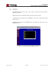


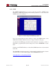
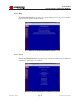
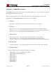
Table Of Contents
- 1.0 INTRODUCTION
- 2.0 FEATURES & OPTIONS
- 3.0 SAFETY WARNINGS
- 4.0 WARRANTY (summary)
- 5.0 UNPACKING AND INSPECTION
- 6.0 GENERAL SPECIFICATIONS
- 7.0 FRONT PANEL DESCRIPTION
- 8.0 REAR PANEL DESCRIPTION
- 9.0 CURRENT METER & LED INDICATORS
- 10.0 MAKING CONNECTIONS TO THE X100
- 11.0 INSTALLATION
- 12.0 USING THE CONTROLLER WEB BROWSER INTERFACE
- Appendix 1 – SNMP MIB Information
- Appendix 2 – Revision History
- Figure 1 - X100 Compact Integrated DC Power System
- Figure 2 - Front Panels with Bezel Removed
- Figure 3a - Rear Panel – Options A & B
- Figure 3b - Rear Panel – Option C
- Figure 4 - Current Meter and LED Indicators (showing MAJ & FUSE alarms)
- Figure 5 - Controller Status WEB Page (typical)
- Figure 6 - Rectifier Status WEB Page (typical)
- Figure 7 - Controller Factory Calibration WEB Page (typical)
- Figure 8 - Controller Site Installation WEB Page (typical)
- Figure 9 - Alarm Configuration WEB Page (typical)
- Figure 10 - Controller Network Settings (typical)
- Figure 11 - Controller Alarm Log WEB Page (typical)
- Figure 12 - Controller Control Panel WEB Page (typical)
- Figure 13 - Controller System Settings WEB Page (typical)
- Figure 14 - SNMP Configuration WEB Page (typical)
- Figure 15 - Controller Help WEB Page (typical)
- Figure 16 - About UNIPOWER Telecom WEB Page (typical)

Page 43
X100 SERIES
INSTALLATION & OPERATING MANUAL
Manual No. x100-5a
x100-man-Rev5a-0214.indd
Appendix 1 – SNMP MIB Information
The SNMP feature provides status read-out and alarm trapping only. All parameters described in
this appendix are therefore read-only.
Refer to the appropriate sections earlier in the main body of this manual for system set-up.
Parameters for UNIPOWER X100 Remote Access Controller MIB
1. Voltages
Bus Voltage - Description: Live data giving actual voltage of system bus.
2. Currents
Battery Current - Live data giving actual current drawn from or into battery string(s).
Rectier Current - Live data giving actual current drawn from rectier power supply system.
Load Current - Live data giving actual current delivered to the load.
3. Temperatures
Battery Temperature - Live data giving actual temperature of battery string.
External Temperature - Live data giving actual temperature of external sensor.
Controller Temperature - Live data giving actual temperature within the controller enclosure.
4. RectierInfo
Number of Rectiers - Live data giving number of rectiers detected by the controller.
5. Auxiliary Inputs
These are all part of one status ag held within the controller.
Digital Input 1 (Low Voltage Disconnect State)
Digital Input 2 (Fuse/Breaker State)
Digital Input 3
Digital Input 4
Digital Input 5
Digital Input 6
Digital Input 7
Digital Input 8