
Specifications
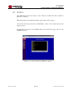


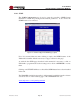
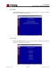
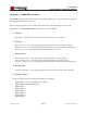
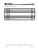
Table Of Contents
- 1.0 INTRODUCTION
- 2.0 FEATURES & OPTIONS
- 3.0 SAFETY WARNINGS
- 4.0 WARRANTY (summary)
- 5.0 UNPACKING AND INSPECTION
- 6.0 GENERAL SPECIFICATIONS
- 7.0 FRONT PANEL DESCRIPTION
- 8.0 REAR PANEL DESCRIPTION
- 9.0 CURRENT METER & LED INDICATORS
- 10.0 MAKING CONNECTIONS TO THE X100
- 11.0 INSTALLATION
- 12.0 USING THE CONTROLLER WEB BROWSER INTERFACE
- Appendix 1 – SNMP MIB Information
- Appendix 2 – Revision History
- Figure 1 - X100 Compact Integrated DC Power System
- Figure 2 - Front Panels with Bezel Removed
- Figure 3a - Rear Panel – Options A & B
- Figure 3b - Rear Panel – Option C
- Figure 4 - Current Meter and LED Indicators (showing MAJ & FUSE alarms)
- Figure 5 - Controller Status WEB Page (typical)
- Figure 6 - Rectifier Status WEB Page (typical)
- Figure 7 - Controller Factory Calibration WEB Page (typical)
- Figure 8 - Controller Site Installation WEB Page (typical)
- Figure 9 - Alarm Configuration WEB Page (typical)
- Figure 10 - Controller Network Settings (typical)
- Figure 11 - Controller Alarm Log WEB Page (typical)
- Figure 12 - Controller Control Panel WEB Page (typical)
- Figure 13 - Controller System Settings WEB Page (typical)
- Figure 14 - SNMP Configuration WEB Page (typical)
- Figure 15 - Controller Help WEB Page (typical)
- Figure 16 - About UNIPOWER Telecom WEB Page (typical)

Page 45
X100 SERIES
INSTALLATION & OPERATING MANUAL
Manual No. x100-5a
x100-man-Rev5a-0214.indd
7. Settings
OVER VOLTAGE ALARM SETTING - Setting for over voltage alarm.
UNDER VOLTAGE ALARM SETTING - Setting for under voltage alarm.
END VOLTAGE ALARM SETTING - Setting for end voltage alarm.
LVD1OFF SETTING - Setting for voltage at the point where LVD1 will be shut off.
LVD1ON SETTING - Setting for voltage at the point where LVD1 will be turned on.
LVD2OFF SETTING - Setting for voltage at the point where LVD2 will be shut off.
LVD2ON SETTING - Setting for voltage at the point where LVD2 will be turned on.
FLOAT VOLTAGE - Voltage setting for the bus in float mode (modified by temp.
compensation).
EQUALIZE VOLTAGE - Voltage setting for the bus in equalization mode.
NOMINAL SYSTEM VOLTAGE - The nominal system voltage (12, 24 or 48).
CONTROLLER OVER TEMPERATURE ALARM - The controller temperature, in degrees
Celsius, above which an over temperature alarm will activate.
BATTERY OVER TEMPERATURE ALARM - The battery temperature, in degrees Celsius,
above which an over temperature alarm will activate.
EXTERNAL OVER TEMPERATURE ALARM - The external temperature, in degrees Celsius,
above which an over temperature alarm will activate.
TEMPERATURE COMPENSATION SLOPE - The parameter applied, in millivolts/°C/cell,
to the oat voltage to achieve temperature compensation.
TEMPERATURE COMPENSATION MAX TEMPERATURE - The temperature above which
no further temperature compensation will be applied.
TEMPERATURE COMPENSATION MIN TEMPERATURE - The temperature below which
no further temperature compensation will be applied.