
Specifications

15
INV2500 & INV5000 SERIES
OPERATING MANUAL
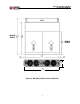
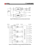
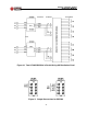
13.4 Figure 10 shows two INV5000s connected in parallel to give 10KVA of AC
output at 115VAC. Note that only 115VAC INV5000s can be used with the
DPAC1UT distribution panel and not the 230VAC INV5000s. 230VAC
INV5000s require breakers on both line sides, and this is not available with
the DPAC1UT. As with the INV2500, the input ground, output ground, chas-
sis ground and AC neutral are all connected in common inside the INV5000
inverter. Note also that only the “T” Option of the DPAC1U can be used with
the INV5000 inverters and that as shown in Figure 10, the A side AC input
terminals must be strapped in parallel, i.e., A1G to A2G, A1N to A2N and
A1L to A2L; in the same way, the B side AC input terminals must also be
strapped in parallel.
14.0 INSTALLATION AND TESTING
14.1 The inverter or inverters may be initially tested either in a rack or on a bench.
For 23-inch rack mounting use panel extenders.
14.2 Put both input and output circuit breakers in the off (down) position. See
Figure 3. For the INV5000, remove the rear safety cover.
14.3 For the INV2500, connect the input battery -48VDC and Return terminals to
the inverter input red and black terminals, respectively, by means of the
Anderson connectors (no. 5916 housings with no. 5952 contacts). Connect
the input ground (green connector) and chassis ground to the system
ground. For the INV5000, connect the input battery to the -48VDC and
48VDC return input bus bars by means of the 1/4-20 studs. Connect the
input ground (10-32 stud) to the system ground. Make sure the correct
polarity is used and make sure the Anderson connectors on the INV2500 are
seated all the way in. Reversed input polarity could cause damage to the
inverter.
14.4 For the INV2500, connect a three-wire AC output cable to the AC output line
(black), neutral (white) and ground (green) terminals by means of the Ander-
son connectors (no. PP15/45 housings with no. 261G2 contacts). For the
INV5000, connect the AC output cable to the proper output screw terminals.
See Figure 11 for the correct connection for 115 or 230VAC output versions.
Connect a load of approximately 10 amperes across the output of the
INV2500 or INV5000.
14.5 To power up the INV2500, turn the DC input circuit breaker on by moving the
toggle to the up position. The fans and Input OK and Sync OK LEDs should