
User's Manual


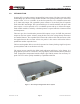


Table Of Contents
- 1.0 INTRODUCTION
- 2.0 FEATURES & OPTIONS
- 3.0 SAFETY WARNINGS
- 4.0 WARRANTY (summary)
- 5.0 UNPACKING AND INSPECTION
- 6.0 GENERAL SPECIFICATIONS
- 7.0 PRINCIPAL OF OPERATION
- 8.0 FRONT PANEL DESCRIPTION
- 9.0 REAR PANEL DESCRIPTION
- 10.0 LED Indicators
- 11.0 MAKING CONNECTIONS TO THE X75
- 12.0 INSTALLATION
- 13.0 USING THE CONTROLLER WEB BROWSER INTERFACE
- Appendix 1 – SNMP MIB Information
- Appendix 2 – Load LVD Configuration (model X75-12-A-GHHIL-S-578 only)
- Appendix 3 – Revision History
- Figure 1 - X75 Compact Integrated DC Power System
- Figure 2 - Block Schematic
- Figure 3a - Front View with Breakers (configuration A)
- Figure 3b - Front View with GMT Fuses (configuration B)
- Figure 4 - Rear Views of Base and Expansion Units
- Figure 5 - LED Indicators
- Figure 6 - Recommended Load Circuit Wire Sizes
- Figure 7 - Battery Temp. Probe & Alarm Relay Connector Pin-Out
- Figure 8 - Ethernet Connector Pin-Out
- Figure 9 - Auxiliary Connector Pin-Out
- Figure 10 - Input Current Ratings
- Figure 11 - Controller Status WEB Page (typical)
- Figure 12 - Rectifier Status WEB Page (typical)
- Figure 13 - Rectifier I²C Addressing
- Figure 14 - Controller Factory Calibration WEB Page (typical)
- Figure 15 - Controller Site Installation WEB Page (typical)
- Figure 16 - Alarm Configuration WEB Page (typical)
- Figure 17 - Controller Network Settings (typical)
- Figure 18 - Controller Alarm Log WEB Page (typical)
- Figure 19 - Controller Control Panel WEB Page (typical)
- Figure 20 - Controller System Settings WEB Page (typical)
- Figure 21 - SNMP Configuration WEB Page (typical)
- Figure 22 - Controller Help WEB Page (typical)
- Figure 23 - About UNIPOWER Telecom WEB Page (typical)

Page 6
X75 SERIES
INSTALLATION & OPERATING MANUAL
Manual No. x75-10b
x75-man-Rev10b-0514.indd
3.0 SAFETY WARNINGS
3.1 The X75 Compact DC Power System operates at voltages that could potentially be
hazardous. Furthermore, inadvertent short circuiting of the system battery and/or
rectier by mis-connection or other error could be harmful. This product should be
handled, tested and installed only by qualied technical persons who are trained in
the use of power systems and are well aware of the hazards involved.
3.2 All connections to the X75 should be carefully checked for errors before applying
power to it.
3.3 SpecicConsiderationsforRackMountedEquipment
3.3.1 Elevated OperatingAmbient - If installed in a closed or multi-unit rack
assembly, the operating ambient temperature of the rack environment may be greater
than room ambient. Therefore, consideration should be given to installing the X75
in an environment compatible with the maximum ambient temperature of 50°C at
full rated load, and at 70°C at derated load at a derating factor of 2.5%/°C from
50°C to 70°C.
3.3.2ReducedAirFlow- Installation of the X75 in a rack should be such that the
amount of air ow required for safe operation of the equipment is not compromised.
3.3.3MechanicalLoading- Mounting of the X75 in the rack should be such that a
hazardous condition is not achieved due to uneven mechanical loading.
3.3.4CircuitOverloading- Consideration should be given to the connection of the
X75 to the supply circuit and the effect that overloading of the circuits might have
on overcurrent protection and supply wiring. Appropriate consideration of the X75
nameplate ratings should be used when addressing this concern.
3.3.5ReliableEarthing- Reliable earthing of rack-mounted equipment should be
maintained. Particular attention should be given to supply connections other than
direct connections to the branch circuit (e.g. use of power strips).”
3.4 The X75 is intended only for installation in a “RESTRICTED ACCESS LOCATION”.
3.5 Input/output short circuit ratings are 5K AIC for terminals connected to breakers
and 450 AIC for terminals connected to GMT type fuses.