
User's Manual


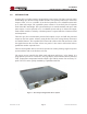
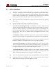


Table Of Contents
- 1.0 INTRODUCTION
- 2.0 FEATURES & OPTIONS
- 3.0 SAFETY WARNINGS
- 4.0 WARRANTY (summary)
- 5.0 UNPACKING AND INSPECTION
- 6.0 GENERAL SPECIFICATIONS
- 7.0 PRINCIPAL OF OPERATION
- 8.0 FRONT PANEL DESCRIPTION
- 9.0 REAR PANEL DESCRIPTION
- 10.0 LED Indicators
- 11.0 MAKING CONNECTIONS TO THE X75
- 12.0 INSTALLATION
- 13.0 USING THE CONTROLLER WEB BROWSER INTERFACE
- Appendix 1 – SNMP MIB Information
- Appendix 2 – Load LVD Configuration (model X75-12-A-GHHIL-S-578 only)
- Appendix 3 – Revision History
- Figure 1 - X75 Compact Integrated DC Power System
- Figure 2 - Block Schematic
- Figure 3a - Front View with Breakers (configuration A)
- Figure 3b - Front View with GMT Fuses (configuration B)
- Figure 4 - Rear Views of Base and Expansion Units
- Figure 5 - LED Indicators
- Figure 6 - Recommended Load Circuit Wire Sizes
- Figure 7 - Battery Temp. Probe & Alarm Relay Connector Pin-Out
- Figure 8 - Ethernet Connector Pin-Out
- Figure 9 - Auxiliary Connector Pin-Out
- Figure 10 - Input Current Ratings
- Figure 11 - Controller Status WEB Page (typical)
- Figure 12 - Rectifier Status WEB Page (typical)
- Figure 13 - Rectifier I²C Addressing
- Figure 14 - Controller Factory Calibration WEB Page (typical)
- Figure 15 - Controller Site Installation WEB Page (typical)
- Figure 16 - Alarm Configuration WEB Page (typical)
- Figure 17 - Controller Network Settings (typical)
- Figure 18 - Controller Alarm Log WEB Page (typical)
- Figure 19 - Controller Control Panel WEB Page (typical)
- Figure 20 - Controller System Settings WEB Page (typical)
- Figure 21 - SNMP Configuration WEB Page (typical)
- Figure 22 - Controller Help WEB Page (typical)
- Figure 23 - About UNIPOWER Telecom WEB Page (typical)

Page 9
X75 SERIES
INSTALLATION & OPERATING MANUAL
Manual No. x75-10b
x75-man-Rev10b-0514.indd
6.4 Safety
The X75 system is compliant with UL60950-1, EN60950-1, CSA22.2-60950-1 and
all other derivatives of the core IEC60950-1 standard 2nd Edition when installed
correctly within a restricted access environment.
The X75 system is CE marked to indicate conformance to the European Union’s
Low Voltage and EMC Directives.
6.5 EMC
The X75 complies with the following Norms when correctly installed.
Conducted Emissions: EN55022, level A
Radiated Emissions: EN55022, level A
ESD: EN61000-4-2, level 4, criterion A - 8kV contact, 15kV
air.
Radiated Immunity: EN61000-4-3, level 3, criterion A - 10V/m.
Surges (power ports): EN61000-4-5, level 1, criterion A - 500V
6.6 Environmental
Operating Temperature: -20°C to 70°C, derating 2.5%/°C from 50°C to 70°C
Storage Temperature: -40°C to 75°C
Humidity: 0% to 95% Non-Condensing
6.7 PhysicalSpecication
Case Material: Steel
Finish: Clear Passivated
Dimensions: 1.72H (43.7) x 17.2W(437) x 14.47D(368)
Rack Width: 19” or 23” using dual purpose kit supplied.
NOTE: Mid-mount is recommended when used in
free space.