
User's Manual


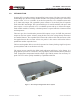


Table Of Contents
- 1.0 INTRODUCTION
- 2.0 FEATURES & OPTIONS
- 3.0 SAFETY WARNINGS
- 4.0 WARRANTY (summary)
- 5.0 UNPACKING AND INSPECTION
- 6.0 GENERAL SPECIFICATIONS
- 7.0 PRINCIPAL OF OPERATION
- 8.0 FRONT PANEL DESCRIPTION
- 9.0 REAR PANEL DESCRIPTION
- 10.0 LED Indicators
- 11.0 MAKING CONNECTIONS TO THE X75
- 12.0 INSTALLATION
- 13.0 USING THE CONTROLLER WEB BROWSER INTERFACE
- Appendix 1 – SNMPv3 MIB Information
- Appendix 2 – Load LVD (special order)
- Appendix 3 – Revision History
- Figure 1 - X75 Compact Integrated DC Power System
- Figure 2 - Block Schematic
- Figure 3a - Front View with Breakers (configuration A)
- Figure 3b - Front View with GMT Fuses (configuration B)
- Figure 4 - Rear Views of Base and Expansion Units
- Figure 5 - LED Indicators
- Figure 6 - Recommended Load Circuit Wire Sizes
- Figure 7 - Battery Temp. Probe & Alarm Relay Connector Pin-Out
- Figure 8 - Ethernet Connector Pin-Out
- Figure 9 - Auxiliary Connector Pin-Out
- Figure 10 - Input Current Ratings
- Figure 11 - Status WEB Page (typical)
- Figure 12 - Rectifier Status WEB Applet (typical)
- Figure 13 - Installation WEB Applet - system tab (typical)
- Figure 14 - Installation WEB Applet - float & tc tab (typical)
- Figure 15 - Installation WEB Applet - battery tab (typical)
- Figure 16 - Installation WEB Applet - float & tc tab (typical)
- Figure 17 - Installation WEB Applet - lvd tab (typical)
- Figure 18 - Installation WEB Applet - digital i/p tab (typical)
- Figure 19 - Installation WEB Applet - rectifiers tab (typical)
- Figure 20 - Installation WEB Applet - shunts tab (typical)
- Figure 21 - Battery Management WEB Applet (typical)
- Figure 22 - Alarm Matrix WEB Applet (typical)
- Figure 23 - Alarm Matrix WEB Applet - matrix options (typical)
- Figure 24 - Alarm Matrix WEB Applet - temperature alarm settings (typical)
- Figure 25 - Alarm Matrix WEB Applet - voltage alarm settings (typical)
- Figure 26 - Alarm Matrix WEB Applet - voltage alarm settings (typical)
- Figure 27 - Alarm Matrix WEB Applet - other alarm settings (typical)
- Figure 28 - Network Settings WEB Applet (typical)
- Figure 29 - Alarm Log WEB Applet (typical)
- Figure 30 - Data Log WEB Applet (typical)
- Figure 31 - Change Password WEB Applet
- Figure 32 - Help WEB Page
- Figure 33 - About WEB Page (typical)

Page 3
X75 SERIES - Mk3 Controller
INSTALLATION & OPERATING MANUAL
Manual No. x75mk3-11
x75-man-Rev11-0815.indd
FIGURES
Figure 1 - X75 Compact Integrated DC Power System ...................................................................4
Figure 2 - Block Schematic ............................................................................................................10
Figure 3a - Front View with Breakers (conguration A) ...............................................................11
Figure 3b - Front View with GMT Fuses (conguration B) ..........................................................11
Figure 4 - Rear Views of Base and Expansion Units .....................................................................12
Figure 5 - LED Indicators ..............................................................................................................15
Figure 6 - Recommended Load Circuit Wire Sizes .......................................................................16
Figure 7 - Battery Temp. Probe & Alarm Relay Connector Pin-Out
.............................................17
Figure 8 - Ethernet Connector Pin-Out ..........................................................................................18
Figure 9 - Auxiliary Connector Pin-Out ........................................................................................18
Figure 10 - Input Current Ratings ..................................................................................................20
Figure 11 - Status WEB Page (typical) ..........................................................................................26
Figure 12 - Rectier Status WEB Applet (typical) ........................................................................28
Figure 13 - Installation WEB Applet - system tab (typical) ..........................................................30
Figure 14 - Installation WEB Applet - oat & tc tab (typical) ......................................................31
Figure 15 - Installation WEB Applet - battery tab (typical) ..........................................................32
Figure 16 - Installation WEB Applet - oat & tc tab (typical) ......................................................33
Figure 17 - Installation WEB Applet - lvd tab (typical) ................................................................34
Figure 18 - Installation WEB Applet - digital i/p tab (typical) ......................................................36
Figure 19 - Installation WEB Applet - rectiers tab (typical)........................................................36
Figure 20 - Installation WEB Applet - shunts tab (typical) ...........................................................37
Figure 21 - Battery Management WEB Applet (typical) ...............................................................38
Figure 22 - Alarm Matrix WEB Applet (typical) ...........................................................................40
Figure 23 - Alarm Matrix WEB Applet - matrix options (typical) ................................................41
Figure 24 - Alarm Matrix WEB Applet - temperature alarm settings (typical) .............................43
Figure 25 - Alarm Matrix WEB Applet - voltage alarm settings (typical) ....................................44
Figure 26 - Alarm Matrix WEB Applet - voltage alarm settings (typical) ....................................44
Figure 27 - Alarm Matrix WEB Applet - other alarm settings (typical) ........................................45
Figure 28 - Network Settings WEB Applet (typical) ....................................................................46
Figure 29 - Alarm Log WEB Applet (typical) ...............................................................................48
Figure 30 - Data Log WEB Applet (typical) ..................................................................................49
Figure 31 - Change Password WEB Applet ...................................................................................52
Figure 32 - Help WEB Page ..........................................................................................................53
Figure 33 - About WEB Page (typical) ..........................................................................................53